- Top
- Technical Info
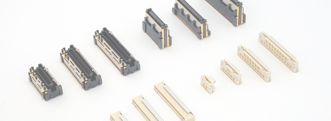
- What is a connector
- How to mount the connector on the board
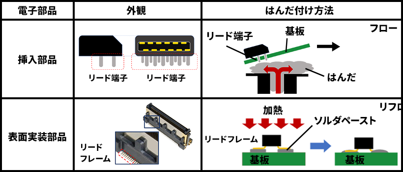
Flow and Reflow: Part Soldering Process
Methods for automating the soldering of parts that started by hand can be broadly divided into "flow implementation" and "reflow implementation". Flow mounting is a method in which a board containing a component is passed over a tank containing melted soldering, and solder is soldered by squirting out solder from the bottom. On the other hand, the reflow implementation is a soldering powder (cream soldering that has been pasted at the same time as the part in advance. ) in the necessary place on the substrate, pass it through a "furnace" under high temperature as if baking it in an oven, melt the solder and implement it. In recent years, surface-mount components called SMT (Surface mount technology) or SMD (Surface mount Device) have become more common in order to effectively utilize both sides of the board and to improve mounting density and productivity, and reflow is naturally becoming mainstream.
Types of each type of mounting on the board of the connector
dip type
This type is plating (VIA) with plating that makes a hole in the board and connects it to the trace, inserts the "lead" of the connector into it, and solders it. As a feature, the mechanical strength of the board mounting can be kept high, but there are also aspects where it is difficult to reduce the size and mount it at high density. In principle, connectors are soldered by hand or flow process, and the disadvantage is that it can not cope with the mainstream reflow process in recent years. However, there are also connectors with special specifications called "pinyin paste" that allow implementation in the reflow process while taking advantage of the advantages of this type (also called "through-hole reflow", "reflow dip", etc.). In this type, cream soldering once extruded out of the through-hole is soldered by sucking it up by capillary action during the process of passing through the reflow furnace.
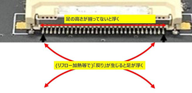
SMT type (lead frame)
This type is suitable for surface mounting, and the lead frame is placed on pads on the board coated with cream soldering and soldered in a reflow oven. Many other board-mounted components such as semiconductors also fall under this type. The legs for connection are arranged in a row in the horizontal direction, and the uniformity of the height of the legs, called coplanarity, is a more important quality control item than the DIP type due to the characteristics of surface mounting. In addition, overheating in the reflow oven can cause deformation and warping of the plastic parts of the connector.
As a feature, it is suitable for miniaturization/high-density mounting compared to the DIP type. On the other hand, in order to make up for the mounting strength to the board, which is relatively inferior, there are many cases where they have attached parts/mechanisms. In addition, since soldering leads are less likely to cause a state called "stub", there is also the advantage that it is easier to design for high-speed transmission than DIP products.

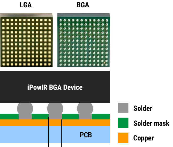
BGA type
Among the surface mounting methods, there are mounting methods on substrates called BGA (Ball Grid Array) and LGA (Land Grid Array), which are particularly used for mounting highly functional semiconductors. Among these, connectors with a mounting form similar to BGA are also appearing on the market.
The advantage is that high-density mounting is possible, and the lead from the connector to the board can be shortened, so it is suitable for high-speed transmission.
On the other hand, unlike semiconductors, stress is applied during Mating, so advanced design verification is required. The structure is somewhat complicated, the cost is high, and the method of inspecting the soldering part (although it has a proven track record in semiconductors) is different from ordinary connectors. I'm here.
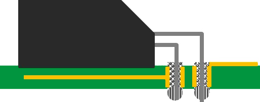
press fit type
There is a method called press-fit for mounting connectors to boards without soldering. This method involves pressing connector leads with a spring structure as shown in the figure into through holes in the board. Unlike any of the mounting methods explained so far, this method is mounted by "pressing evenly from above." Therefore, it cannot be installed at the same time as other mounted components, and the connector mounting must be done in a separate process. Also, a special jig is required to press evenly, and when Pin Counts is increased, a suitable force is required, but there are many cases where the pressing force needs to be controlled within a narrow range due to strength constraints.
Like DIP, miniaturization was originally a challenge, but in recent years there are press-fit connectors of fairly small sizes, and many products that support high-density mounting by gridding have been released. Also, like DIP, high-speed transmission was hindered by stubs, but there are also cases where high-speed transmission is made possible by using connectors with short legs and using a method called "back drilling" to drill holes on the opposite side of the board and remove the metal parts that will become stubs.
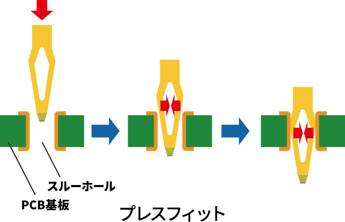
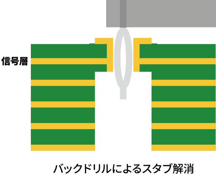
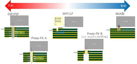
Image of high-speed transmission
As explained in each item, the image of high-speed transmission support when the SMT type is standard is shown below. However, even if it is the same type, it can be improved by various design ingenuity, and the internal structure of the connector also has a large impact. Consider the following as a general guideline only.
For information on Other high-High-speed transmission Connector, please click here.
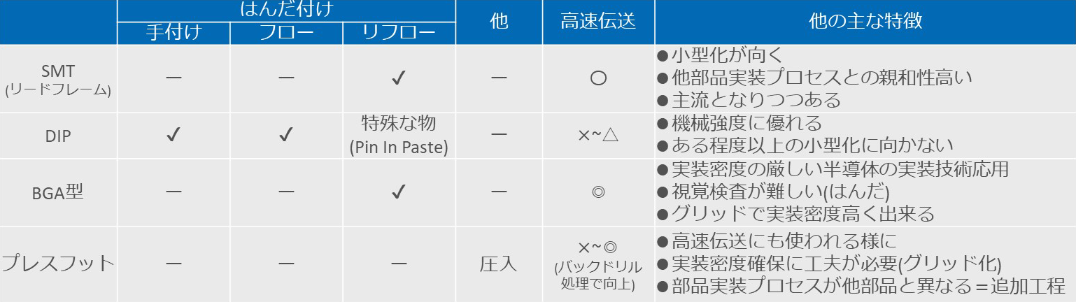
Other characteristics of each type
Below is a summary of the basic features of each type and the corresponding mounting method. At present, the SMT type, which has become mainstream in recent years, is said to be the most balanced method. IRISO mainly uses the SMT type, and produces a variety of products including regular DIP products and DIP products that are compatible with pin-in-paste. We plan to develop BGA and press-fit products according to needs.