

イリソ電子工業の『コラム』では、コネクタに直接的・間接的にかかわる技術的な内容をわかりやすく説明しています。
特に「専門家の方に教えてもらったけど、難しくて良くわからなかった・・・・」というものを、できる限り専門的な知識がなくとも解釈できるような内容をお届けしています。その道のスペシャリスト向けではなく、門外漢の方が「話についていけるように」というレベルにとどめて説明を心がけており、これをきっかけに「より深く知りたい」と感じ、自分で調査学習される方が出ていらっしゃれば、大変うれしいことだと思います。
コンテンツ一覧
周波数とデータレート
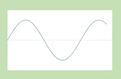
「GHz」と「Gbps」の違いはご存じですか?
この2つは、それぞれ「周波数」と「データレート」の単位です。本記事では「GHz」と「Gbps」の違い、「周波数」と「データレート」に関する言葉や関係等で混乱している方にも、なるべく「腑に落ちた」状態で理解いただけるように説明しています。
また、本記事は『周波数ひずみとコーディング』の前編記事です。
周波数ひずみとコーディング
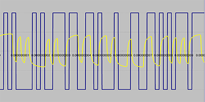
『周波数とデータレート』の後編記事です。
「周波数とデータレート」をお読みでない方は、まずそちらからご参照いただけると幸いです。 前回よりはやや難しくなるかもしれませんが、あくまでコネクタメーカの目線、いわば素人目線から理解でき、かつ必要となる範囲を切り取った内容を簡単にまとめています。高速伝送の1トピックとして、お読みください。
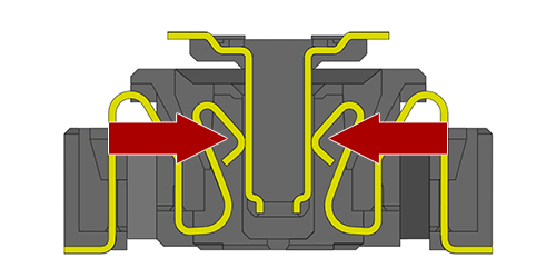
「フローティング」と「高速伝送」は相反する要求?
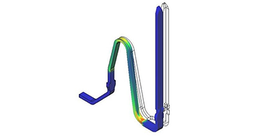
「フローティング」と「高速伝送」。この機能・性能はトレードオフの関係にありますが、その両立に向けて、イリソ電子工業でも当社以外のコネクタメーカ様でも、コネクタメーカの腕の見せどころとして、技術・開発力を費やしています。なぜこの2つはトレードオフの関係にあるのか、どのように両立させているのか。できるだけ簡単にご説明します。
「抵抗損失」と「誘電損失」 信号が熱に変わって小さくなる?
高速伝送領域において、伝送路などを経由するとなぜ信号は「減衰してしまう=小さくなってしまう」のでしょうか?信号の減衰にはいくつか原因があります。本記事は、「電気抵抗による損失」と「誘電損失」という伝送路周辺の材質に依存する損失をテーマに、昨今注目を集める低損失部材等の製品の技術的な背景、なぜ、そして何に対して優れているのかを、大まかに説明しています。
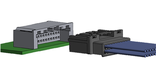
シングルエンド伝送と差動伝送におけるコネクタ性能差の理由
差動伝送のコネクタを、時折「シングルエンドで使った場合はどうなのか?」というご質問を社内外からいただきます。残念ながら「少なくとも同等の性能は期待できません・・・・」という回答になる場合がほとんどです。本記事では、差動伝送とシングルエンド伝送の特徴から、なぜコネクタの性能に違いが生じるのかに、可能な限り「イメージとしてとらえられるような」形で説明をしています。
高耐熱コネクタってなんだろう?
“高耐熱コネクタ”には、耐熱温度80℃くらいのものから果ては680℃対応まで様々な製品があります。本記事では「機器内で使用される基板接続用のコネクタ」を中心に、何をもって高耐熱としているのか、用途、技術的な課題とアプローチ、特殊な事例などを交えて説明します。
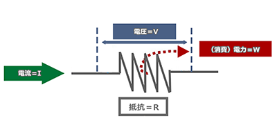
電流を複数ピンに分流した場合、何A流せるか?
コネクタの分流対応は、各メーカーで異なります。たとえば、「このコネクタ定格1.0Aだけど、3ピン使って3.0A流したい」という要望に対し、分流を推奨するメーカーと推奨しないメーカーといます。それは、なぜでしょうか。本記事では、通電によるコネクタ発熱から大電流への対応に触れながら、分流について考察します。
コネクタの端子にめっきをするのはなぜか?
コネクタに、めっきはつきものです。ただ、めっきの種類や構成は、結構複雑です。このページでは、コネクタに使用される主な金属と特徴やコネクタのめっき 2つの機能、ニッケルめっきの機能、金めっきの弱点と対策等について、できるだけ簡単に説明します。
コネクタは戦っています!? コネクタの接続不良の要因と対策

電気接続において、「金属同士が触っていれば導通する」というのは、実は全く間違いではないのですが、この触るは、「しっかり正しく触る」である必要があります。加えて「余計なところに触らない」、「その状態を維持する」ことも必要になります。しかしながら、コネクタが使用される環境ではこれらを阻害するものがたくさんいるのです。今回は、接続不良の要因と対応について説明していきます。
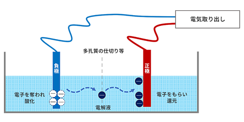
ショート不良とオープン不良でどちらが危険?活線挿抜って何?
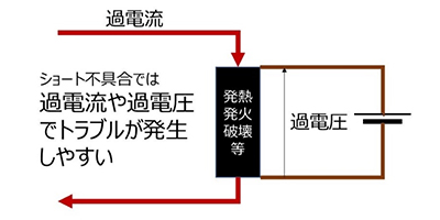
コネクタの不具合を大分するとショート不良とオープン不良の2つになりますが、2つのうちどちらの方がより避けるべき不具合なのでしょうか? 2つの不具合の違いや、活線挿抜/ホットプラグに使われるコネクタのポイント、「電気による破壊を避ける」という点で共通するESD対応の話などについてまとめたコラムとなります。
コネクタの導体と絶縁体
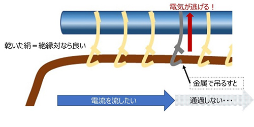
コネクタ誕生に至るまでの歴史や周辺のトリビアに触れながら、電線との目的の差からくる材料の違いや、コネクタ材料であるプラスチックと金属について掘り下げて説明していきます。
データレートと搬送波周波数とコネクタの関係は?
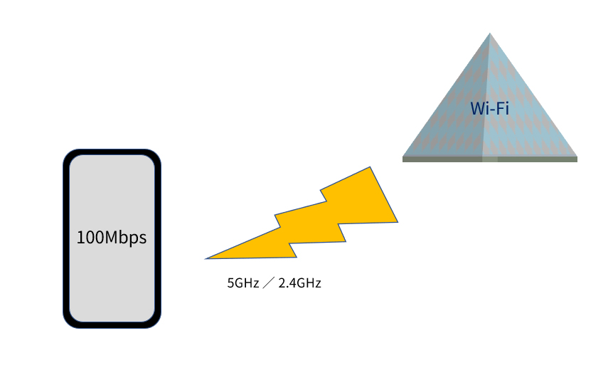
アナログ変調とデジタル変調の違い等に触れつつ、無線で送るような高速信号についてコネクタはどうような性能を求められるのかについて説明します。
機械的共振と電気的共振
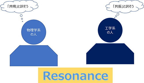
複数の状況で用いられる共振/共鳴の言葉の意味を整理しながら、機械的共振と電気的共振の個別の技術的な部分を掘り下げて説明します。