
- Top
- Technical Info
- column
- Which is more dangerous, a short circuit or an open circuit? What is live insertion?
Which is more dangerous, a short circuit or an open circuit? What is live insertion?
As I wrote in another article in this column, "Connectors are fighting!? Causes of poor connections and how to deal with them," connector problems can be largely divided into the following two categories:
- Short circuit/Short circuit and incorrect wiring → Connecting something that should not be connected
- Non-conductive (open) → Not connected where it should be
There are two types:
Our challenge as connector manufacturers is to prevent either of these from occurring, but of the two, which of these defects is more important to avoid?
To put it simply, although there are exceptions, in most cases it is a short circuit that leads to, for example, a fire or serious equipment failure.
This article is a sister edition of the earlier article, "Connectors are fighting!? Causes of connection problems and how to deal with them," and covers the differences in malfunctions, key points for connectors used for live insertion/hot plugging, and ESD compliance, which is common in terms of "avoiding damage caused by electricity."
Various examples of short circuit defects
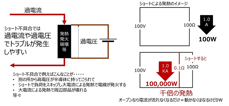
Figure 1. Image of a short circuit
The diagram is for illustrative purposes only.
Some people may have experienced dust accumulating in an electrical outlet, causing smoke or fire, or batteries shorting out with wires or nearby electrical wires, causing them to become extremely hot (I've experienced both...). These are easy-to-understand examples of common short-circuit problems. Also, when you look at recall news about home appliances and automobiles that involve connectors or wiring, I think there are many news stories that make you think, "Oh, so short circuits are more dangerous."
Of course, if an open failure occurs during operation, there is a risk that important things, such as the safety functions of the device, may stop mid-operation.
In addition, in exceptional cases such as when the current is divided, some of the terminals may become open and an overcurrent may flow through the remaining terminals, causing abnormal heat generation.
(I touched on this briefly at the end of another article in this column, "How many amps can flow if the current is divided among multiple pins?", which provides a simple discussion of heat generation due to current division and resistance variations, so I hope you will also take a look at this.)
Also, improper earth connections in the power supply system are one of the factors that increase the risk of accidents, but still, short circuits seem to pose a greater risk in comparison. The difference is particularly noticeable when limited to the dangers immediately after connection.
Furthermore, when it comes to failure modes for electronic components, not just connectors, an open mode is preferred over a short mode, which can lead directly to failure of the entire device (although there are cases where you can't choose, and the best thing is that it doesn't break).
Now, there are cases where the problems caused by this short mode need to be prevented on a more expanded scale.
This is how it supports live insertion and removal.
What is live plugging?
There is also something called hot insertion/removal, hot swapping, hot plugging, etc. It is a device that has a connector that can be attached and detached while the power is on.
The circuit side, or the mechanism of the device, must be able to accommodate insertion and removal, and the connector structure has several mechanisms to help this.
In some cases the connector helps make hot swapping possible.
Mating sequence: Take turns mating for safety
A familiar example of a device that can be plugged in and out is USB.
This shape allows the power and GND terminals Mating Mating first, followed by the signal terminals.
The time difference is only a few hundredths of a second, and this is called the mating sequence.
Figure 2. USB memory stick terminal shape

Figure 3. Is there no potential difference between a PC and a USB memory stick?
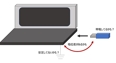
So why are the power and GND terminals Mating first, followed by the signal terminals?
For example, imagine you are trying to insert a USB stick into your PC and you see something like the image in Figure 3.
Here, there will be "electrical harmony" between the PC and the USB memory stick. However, there may be a difference in their "electric potential." Ideally, the housing of a device should be grounded, i.e., dropped to an absolute 0V level, but in reality, this is surprisingly difficult. Also, small memory sticks and the like may become charged while placed somewhere. When such devices are Mating, the potential difference gives an unintended voltage "somewhere," and a current flows into the side with the lower potential to eliminate the potential difference.
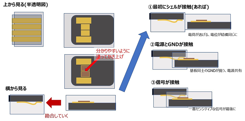
The idea of the mating sequence is roughly as follows:
- Sensitive parts should be balanced before touching each other to avoid applying strange voltages.
- Let's let the current that flows in for potential matching escape to a place where it can flow.
For example, in the case of Figure 4, which is an image of a USB TYPE-A connector, the shells that connect to the housing first connect to each other, and the current that eliminates the mismatch flows out there. After that, the boards are matched at the power supply/GND, and finally the signal is connected.
Are ESD countermeasures and hot-plugging similar?
As an aside, in terms of protecting circuits from inflowing current, there is also the impact of ESD. I think the points to be mindful of are quite similar to hot-plugging. One of the measures we have implemented is a packaging format (optional) that prevents components from becoming electrostatically charged.
We also sell our own proprietary ESD protection devices. Although there are an increasing number of products that have been designed with circuit configurations and have resistance on the semiconductor device side, many customers use these as another layer of protection. That was just a little PR.
Non-USB mating sequence examples
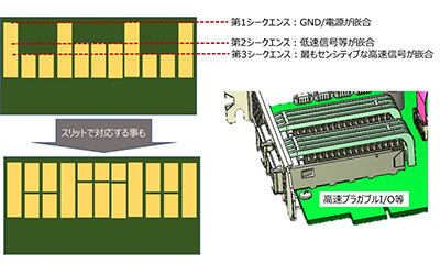
Returning to the subject of mating sequences, there are many other examples besides USB. There are also cases where sequences are set up in more stages than just two. Sequences can also be set up on the board side for card edges and high-speed I/O used in storage devices and communication devices, as well as on cable-side connector parts called paddle cards made of boards.
In those,
① Power supply/GND
② Low-speed control and ID signals
③ The most sensitive high-speed transmission signal
In many cases, Mating is divided into three stages. In the case of paddle cards, the Mating pattern may be completely shifted, but there are also many cases where a slit is made in the middle instead.
It doesn't always go straight in - what to do if it goes in at an angle
Worst-case analysis of tolerances is performed on various mechanical parts. Of course, it is also performed on connectors. The idea is that even if all dimensional tolerances are aligned on the unfavorable side, the guaranteed functions will be met, but with live insertion and removal, a little extra thought must be given.
For now, it's just the parts related to simple connections.
- No short or open defects occur when the connectors are Mating (all connectors)
- During Mating process, there should be no short circuits or mis-conductivity, even if they are accidentally touched (especially when hot-plugging or plugging).
This kind of approach as in 2., which is not something you need to worry about when powering up a circuit after connection, is required for live insertion and removal.
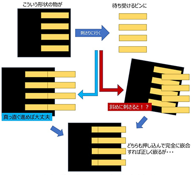
Let's look at a simplified example to see what we care about here.
Imagine a connector with evenly spaced terminals that are being inserted into evenly spaced pins.
If the connector goes straight down to the pins, they will meet correctly. But what if you go at an angle? At some angles, one connector contact will straddle two pins.
If Mating, they will both Mating correctly, but in the case of live insertion/removal, where "electricity is present before connection," the diagonal insertion in the diagram could lead to an accident.
Therefore, the connector needs to have a structure that prevents this from happening.
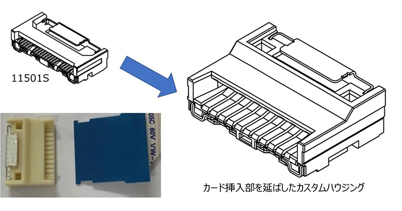
As a concrete example, the figure on the right shows a custom connector that we have developed in the past.
This is a customized product based on our proud Auto I-Lock structure product, the 11501S series.
Previously, we had a customer who wanted to perform live insertion and removal with an FPC connection, so we created a custom housing with a long nose to meet the customer's request. With this connector, the guide leading up to Mating is long, so the FPC is forced to the angle and position during that time, and the terminals do not come into contact until they are in the correct position, preventing the above-mentioned accidents.
So, if we were to do everything this way, it would be that for customers who want to place the connector in as small an area as possible on the board and who do not perform live insertion and removal, the connector would be unnecessarily large, so the regular 11501S is much easier to use. The request for live insertion and removal with FPC is not a very popular one, so that is why we decided to develop and sell it as a custom connector.
Electric shock prevention measures
Well, the connector isn't the only thing you need to be concerned about when plugging in or unplugging a live wire. There could also be foreign objects that could cause a short circuit, and if someone touches it, it could cause not only machine damage but also electric shock depending on the output.
As a simple example, let's look at the side of a PC.
Newer connectors may not have TYPE-A, and there may be exceptions regarding the orientation, but as far as I know, when arranged side-by-side, the connectors are generally arranged so that the USB-TYPE-A terminal faces downwards. In the unlikely event that a small metal piece rolls in, it seems less likely to cause a short circuit if the terminal faces downwards than if it faces upwards. I've never seen anything that clearly explains the reason, but it seems like such a countermeasure idea is incorporated into even small details like this.
Connectors for more delicate devices and high-speed communication equipment may be equipped with dust caps or conductive dust/ESD caps that also serve as ESD protection. In the case of live insertion and removal, such considerations are often taken into account even when the connector is not inserted.
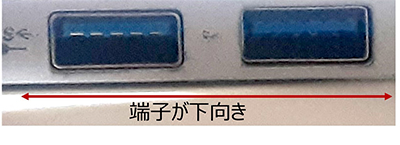
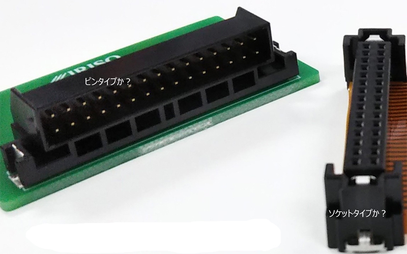
Figure 9. Examples of pin (plug) side and Socket side
The connector side that waits for hot insertion and removal is often designed to prevent fingers from getting caught in it as a precaution against electric shock.
Additionally, for connectors used in vehicles, Socket are preferred on the cable side, which is the side that is touched most frequently.
In many cases, a pin (plug) type is desired on the board side, but in certain live insertion/removal points, a Socket type connector is sometimes used on the board side instead of the pin type to prevent electric shock.
One of the standards related to this is the IP standard (although waterproofing tends to be the only thing that gets focused on).
There are standards for what can be prevented from entering through the structure, with IP2X being unable to be touched (entered) by fingers, 3X being unable to be touched (entered) by the tip of a screwdriver or other tool, and 4X being unable to be touched by wires. Such measures are necessary to ensure the safety of live insertion and removal. Of course, if there is a risk of water entering, the structure following the letters such as IP66 and 67 must also be high. For more information on this, please also refer to "IPXX: Tests and standards for preventing ingress of foreign objects" in the separate article in this column, "Connectors are fighting!? Causes of poor connection and how to deal with them."
summary
This time, we started by explaining the difference in risk between short circuits and open circuits, and then mainly explained the key points of connectors used for live insertion and removal.
There are also many examples where the optimal connector does not necessarily match whether hot-plug or not. It is our important responsibility to develop new products that meet the needs of our customers.
At the same time, we believe that one of our important roles as a connector manufacturer is to work with customers to select the best connectors from those currently available.
We can offer suggestions from various perspectives on what connectors are best suited for the applications you are currently considering. Please feel free to contact our sales department or feel free to contact us on our website. We will be very happy to assist you!