
- Top
- Technical Info
- column
- Are "Floating structure" and "high-speed transmission" contradictory requirements?
Can "Floating structure" and "high-speed transmission" be compatible?
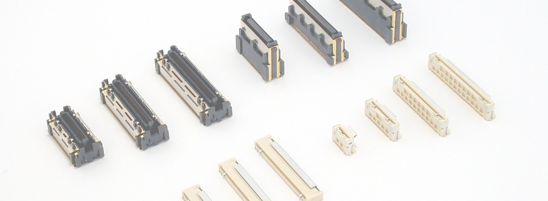
In October 2020, at the same time as CEATEC, we announced the "10143 Series" as Board to Board Connectors that combines Floating structure with high-speed transmission. (Verification of 25Gbps compatibility was also completed by August 2021.)
The reason why I purposely wrote "to be compatible" is that there is a trade-off between these two functions and performance. You may have also seen connector manufacturers other than our company, in the release of products with similar concepts, with the nuance of "compatibilizing conflicting requirements." This issue is exactly where we, connector manufacturers, can show our skills, and it is one of the areas where we are spending our technology and development capabilities.
However, I feel that the explanation is only vaguely "contradictory", and the point "why is it contradictory?" The people involved may say, "It's common sense," and for those who use the product, it may be a story that says, "That's what it is." Still, there may be some people who are interested in this theme. For such people, the content of this time is "Let's explain as simply as possible".
About Floating Connector
What is a Floating Connector?
Floating structure means floating, and a connector with a Floating area is called a Floating Connector. It is also called "Floating connector" as it is. Connectors that connect boards together often have this function.
Feature 1: Absorbs misalignment when mating multiple connectors
So what is the purpose of "having a Floating area"?
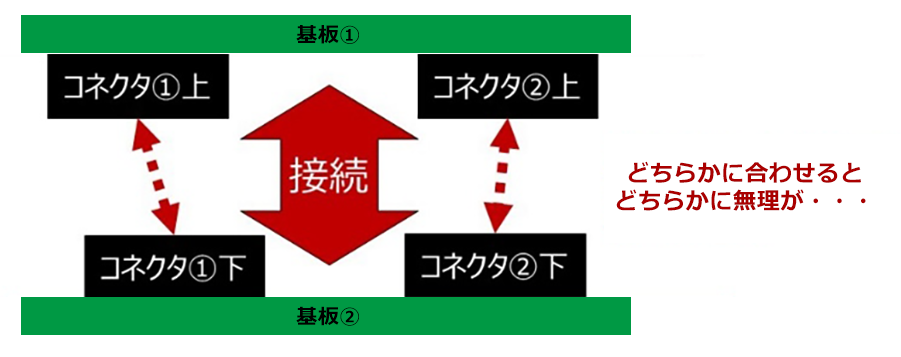
As electronic devices become more sophisticated, it is sometimes necessary to connect two boards using two or more connectors. For example, if there are two connectors as shown in the figure below, the "misalignment" that occurs when mounting the connectors on the board cannot be eliminated. If this deviation exceeds a certain amount, it will be difficult to Mating the two connectors at the same time. Even if the connector can be assembled somehow, stress will always be applied to the mounting part of the connector on the board, which is the soldering part. Floating Connector are designed to absorb this misalignment through "Floating".
Feature 2: Improved assembly
In addition to the mounting misalignment on the board, it is possible to mitigate the influence of the position between boards that is forced when assembling the housing. Connectors usually use springy terminals for connection, so the most typical Floating structure is a structure in which this shape is devised to provide a range of Floating. Having a certain range of Floating makes it easier to assemble equipment and gives flexibility in mounting accuracy and design.
Important point for high-speed transmission "Characteristic impedance"
Characteristic impedance is important
Now, let's move on to the important points for connectors to support "high-speed transmission." There are several important parameters for assessing a transmission line for high-speed transmission. Among them, characteristic impedance is particularly important for transmission line components with relatively short distances, such as connectors.
What is characteristic impedance?
As some of you may know, I would like to explain a little about characteristic impedance.
A high-frequency signal determines the balance of current and voltage that can "exist" when passing through a specific transmission path, component or part that is large enough for its wavelength. This is a natural phenomenon, it's like a rule. And the characteristic impedance is the ratio of current and voltage at this time (current/voltage = so the unit is Ω, the same as resistance).
The phenomenon of "signal reflection"
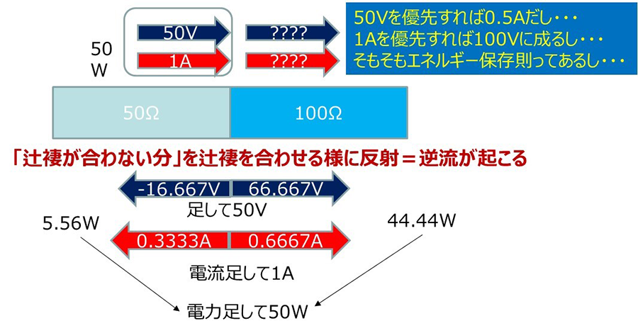
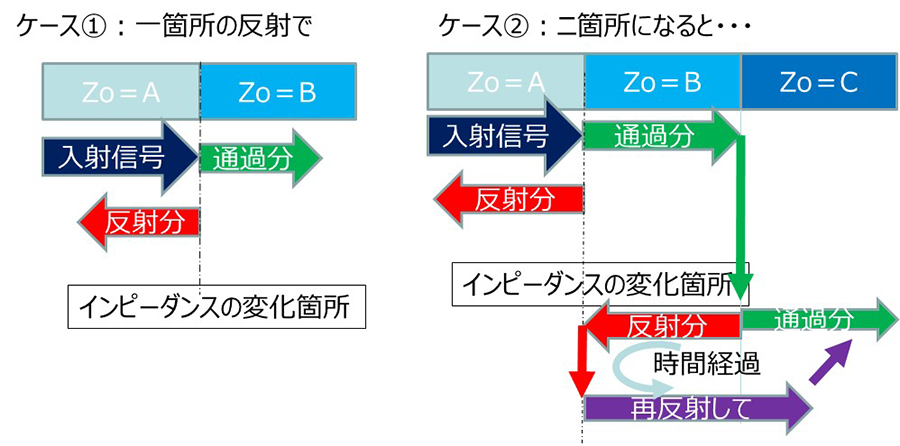
The problem is what happens if this is different for consecutive objects, points, and adjacent states. A simple example is shown below. A signal voltage of 50V traveling through a characteristic impedance of 50Ω is accompanied by a current of 1A. What will happen if this intrudes into the characteristic impedance of 100Ω? In an electric signal, "voltage", "current", and "power" must all be continuous in the process of its transmission, but in this case, it doesn't make sense to intrude normally. A phenomenon occurs in which part of the signal "reverses" so as to make sense of it. This is called "reflection" and occurs when there is a discontinuity in the characteristic impedance.
Why are reflections a problem?
So how does this reflection adversely affect signal transmission?
As shown in the figure below, the simplest problem is that "signal energy is reduced due to reflection = the amount of signal that passes through is reduced". In addition, a more serious problem is that when reflections occur at two or more locations, the past signal components join the current signal due to re-reflection, resulting in noise.
Floating structure and characteristic impedance
Next, we will explain the characteristic impedance of a connector with a Floating structure.
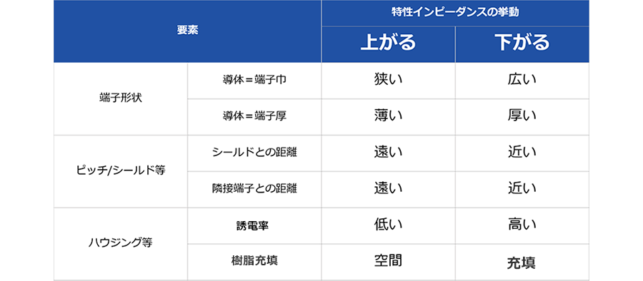
Connectors are generally constructed by assembling "terminals", which are mainly made of springy metal such as copper, into a resin part called a "housing". The characteristic impedance of a connector is determined by the relationship between the shape, size comparison, and sense of distance between the metal and resin parts. The table below briefly summarizes major examples where the characteristic impedance increases (increases) and decreases (decreases). What I would like you to read from here is that "the characteristic impedance changes as the shape of the terminal or housing changes."
Floating Connector with complicated part shape
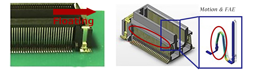
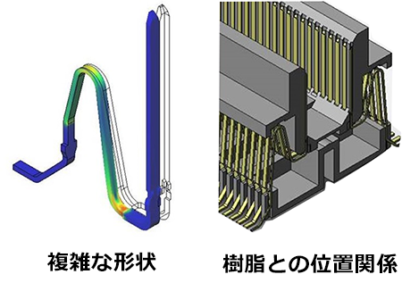
On the other hand, as shown in the figure, the shape of the terminal of the Floating Connector becomes complicated, and the positional relationship with the resin part has many changes in the direction of the signal path. Therefore, the characteristic impedance tends to change easily inside the connector.
At this time, as a design ingenuity, for example, at the point where the characteristic impedance decreases, another element is used to increase the change. However, even if we try to widen the width of the terminal where the resin does not cover it, the spring force of that part will be too strong and it will not work.
It is important to "make"
In addition, while satisfying both mechanical and electrical characteristics, productivity = cost of the product must also be considered. Selecting an unnecessarily complicated shape will not achieve assembly, or at best a very complicated process will be required. The terminal shape, etc. mentioned in the previous example, terminal processing, and assembly of the housing pose a mountain of challenges. It is the manufacturer's responsibility to bring products to the market at a price appropriate for added value and to provide a stable supply. Therefore, except for expensive custom products that are made under extreme circumstances, ensuring productivity is one of the constraints.
in the near future
Of course, innovation in production technology increases the degree of freedom in design, so we are also working on small things every day. In the future, it may be possible to introduce new manufacturing methods and use 3D printers for both metal and resin (or composite and mold). The effective use of laser processing technology, which has evolved remarkably in recent years, will also progress, and a completely different manufacturing method may be developed. When that happens, I'm excited to think that the structure that I had given up on until now might become a mass-produced product.
In summary, the development of a connector with "Floating structure", "stable characteristic impedance", and "structure with good productivity" are the challenges that establish conflicting requirements, and each connector manufacturer is competing fiercely. will be
The frequency and the size of the part where the characteristic impedance must be considered
physical size and frequency
From the explanation so far, some of you may have wondered, "I understand that reflection is a problem, but why is it only a problem with high speed (high frequency)? What about low frequency signals?" In fact, the issues raised in the previous section become more pronounced at higher frequencies. The reason is "the frequency and the size of the part where the characteristic impedance (of the part or part) must be considered".
signal wavelength
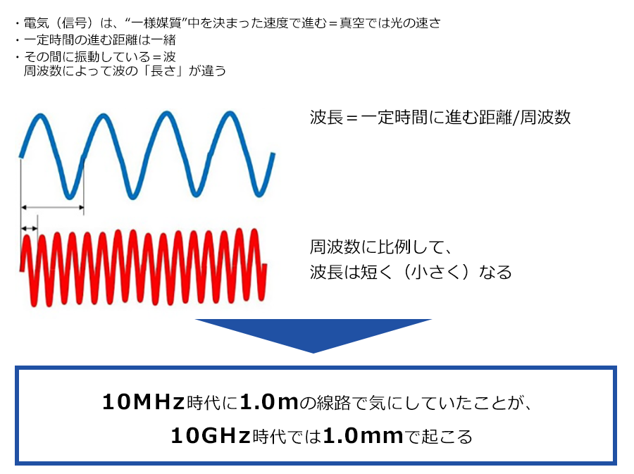
Electrical signals = AC signals have a length called "wavelength". As shown in the figure below, this wavelength becomes shorter as the frequency increases. Although it is written in a slightly crude way, if it is sufficiently short for this wavelength, "(a slight) disturbance of the characteristic impedance can be ignored."
What size should I consider?
However, it is surprisingly difficult to say, "From what ratio should we be concerned?" It also depends on the size of the disturbance. Even at the level of university textbooks, there is a description that if "1/4 x λ (wavelength) >> physical length" can be ignored (exactly whether it is treated as a distributed constant circuit or a lumped constant circuit This is not a correct expression, but I will explain about distributed constant circuits and lumped constant circuits on another occasion. Based on my personal experience, I have an image that the effect starts at about 1/20th of the wavelength, and if it is about 1/10th of the wavelength, it cannot be ignored. More precisely, it can be found by subjecting individual product models to electromagnetic field analysis such as HFSS.
it's about the image
The size to be considered is "What was happening in units of ``Km'' in the telephone communication era has come to occur in units of ``m'' when communication speeds have risen to ``Mbps''. That is ``Gbps''. In the current era, it is occurring in units of "mm".
As an extra bit, let me add "image story", for example, imagine that there is a hole with a diameter of 20 cm in the road. Even if an elephant walks by, it will not notice the hole. If you're a human, an adult might stumble, and if you're a child, your foot might get stuck in a deep hole, even if it's a shallow hole. If you pass by a hedgehog, it will fall into the hole, and if it is a deep hole, you may never get out again. You can imagine that the size of the body of each passer is the wavelength, the size of the hole is the part or part, and the depth of the hole is the change in impedance.
Summary of physical size and frequency
Even if the connector had a disturbance in the characteristic impedance, it was a relatively small hole when viewed from the signal. However, as signal speeds have increased and wavelengths have become shorter, which means that connectors have become smaller, we are now in an age where even minor structural changes inside connectors can affect signal transmission. That's why "both Floating structure and high-speed transmission are compatible" can be a product feature = selling point.
Should we consider only the characteristic impedance?
Is it enough to consider only the characteristic impedance for high-speed transmission?
Transmission parameters that are of concern to those who use various transmission standards and connectors are those that are directly linked to actual operation, and are considered much more important and useful than characteristic impedance. Even at our company, most of the time we place importance on such parameters in product evaluation and specification. However, in connectors, the root cause, which is the root cause, is "reflection due to changes in characteristic impedance," which can be said to determine or worsen these parameters.
Negative effects of reflection
For example, return loss, which is one of the most valued S-parameters, indicates reflection, and reflection is a major factor in deterioration of insertion loss in connectors with short electrical lengths. In addition, reflection points have strong coupling, degrading crosstalk characteristics, and antennaization due to resonance due to multipoint reflection has a large impact on crosstalk and EMC. Characteristic impedance, especially local ones, can change the degree of impact on transmission performance depending on its subtle movements, making it difficult to simply specify quantitative values such as XX to YY. Therefore, in recent years, mainly the more practical frequency-domain transmission parameters have become valid specifications. On the other hand, characteristic impedance is important when viewed as a "connector design", and the approach of stabilizing it (reducing variation) leads to high-speed transmission.
summary
This time, with the theme of the difficulty of achieving both a Floating structure mechanism and high-speed transmission characteristics, I explained the reasons and a rough technical background. It is one of the themes that not only our company but also current connector makers are seriously working on, and I would like to tell you a little bit about the hardships. We would like to be at the top of the industry, especially in the area of "both Floating structure and high-speed transmission", and we are working hard every day to achieve this goal. On the other hand, when I see a wonderful concept in the release of a new product by another company in the same industry, I feel a unique feeling of both frustration and joy. By working together in this way, I hope to continue contributing to connecting high-speed signals in various places.
Here you can find our various initiatives for high-High-speed transmission Connector. Please take a look.