

- Top
- Technical Info
- Connector Glossary
- characteristic impedance
Characteristic impedance
Characteristic impedance is a value unique to a transmission line, expressed as the ratio of voltage to current of a traveling wave propagating through the transmission line.
The unit is ohms (Ω) (voltage value/current value).
In high-speed signals, circuit board wiring, cables, and connectors are all part of the transmission path. If the characteristic impedance changes along the transmission path or does not match the impedance of the termination, part of the signal will be reflected, causing waveform distortion and fluctuations in the received signal level. As a result, communication errors and malfunctions are more likely to occur.
Characteristic impedance, unlike DC resistance, is an inherent electrical characteristic determined by the structure and materials of the transmission line.
In an ideal lossless transmission line, the characteristic impedance is expressed by the following equation:
Z0 = √(L/C)
L: Inductance per unit length
C: Capacitance per unit length
In other words, characteristic impedance is not determined solely by external resistance, but also by the width and spacing of the conductors, the type and thickness of the insulator, and the surrounding structure.
Why is characteristic impedance important?
Characteristic impedance is important because discontinuities in it or mismatches with terminations can cause signal reflection.
When the characteristic impedance changes along the transmission path, a portion of the signal is reflected back to the sender at the boundary.
This is "reflection".
When reflected signals overlap with the original signals, the following degradation in signal quality occurs:
- The waveform is distorted.
- Jitter increases
- Eye pattern worsens
- Return loss worsens
- The received signal level fluctuates.
These factors reduce the margin for correctly interpreting signals, making communication errors and malfunctions more likely. The impact is particularly greater for signals with fast rise times and high frequencies.
Why does reflection occur when the characteristic impedance is discontinuous?
Reflections occur at boundaries where characteristic impedance changes, or at terminations where the impedance of the transmission line and the load do not match.
The relationship between voltage and current in a traveling wave is determined by its characteristic impedance. If this value changes at a boundary, some of the signal will be reflected instead of traveling forward.
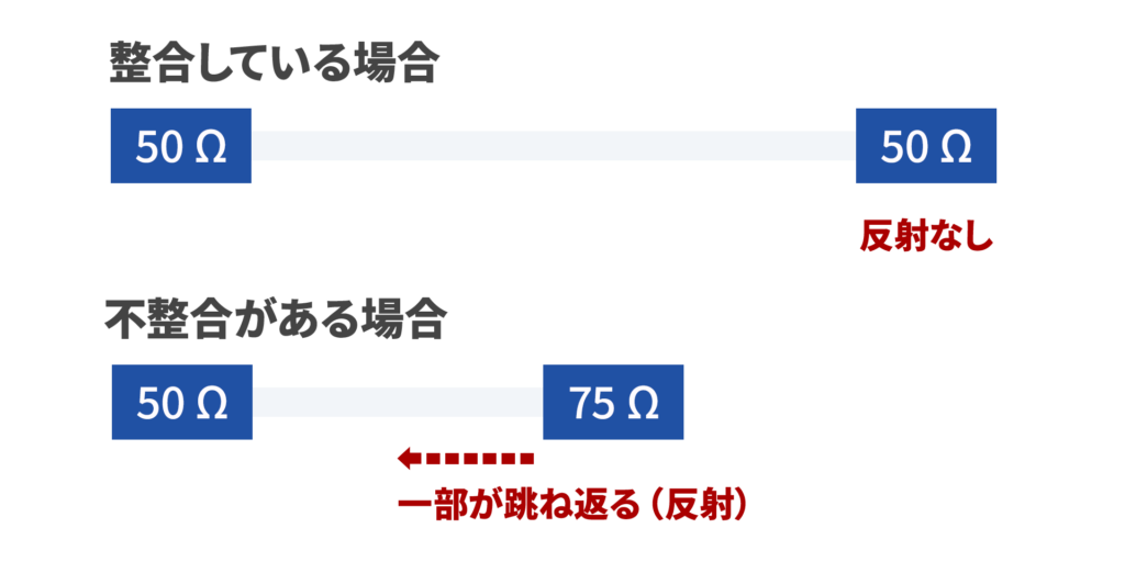
Therefore, in high-speed transmission, it is important to maintain continuity of characteristic impedance throughout the entire transmission path, including the circuit board, cables, and connectors.
Furthermore, the process of appropriately matching the impedance of the transmission line and the destination to suppress reflections is called impedance matching.
Characteristic impedance is also important for connectors.
A connector is not simply an electrical connection point.
In high-frequency and high-speed transmission, connectors also function as part of the transmission path.
Therefore, if the continuity of characteristic impedance is compromised within the connector, reflections occur, resulting in a decrease in signal quality.
Main factors causing variation in characteristic impedance within a connector
- Changes in terminal arrangement and pitch
- Changes in contact shape
- Local shape differences due to spring structure, etc.
- Shield and shell placement
- Mixture of air layer and resin part
- Variation in the distance between differential pairs
- Non-uniform GND placement
High-speed connectors require designs that minimize these effects and maintain continuity of characteristic impedance throughout the entire transmission path.
Typical characteristic impedance values (50Ω, 75Ω, 90Ω, 100Ω)
Characteristic impedance has typical values defined for each application and interface.
Commonly used values
- 50Ω: RF circuits, single-ended wiring, coaxial cables, etc.
- 75Ω: Coaxial cables for video signals, etc.
- 90Ω differential: USB, etc.
- 100Ω differential: HDMI, LVDS, etc.
Why are 50Ω and 100Ω so common?
50Ω offers a good balance of loss, power handling capacity, and ease of design, and is widely used in RF circuits and coaxial transmission.
On the other hand, 100Ω differential impedance is adopted as a standard value in many high-speed differential interfaces.
Therefore, when designing and selecting connectors, it is necessary to ensure that they meet the specifications for the target characteristic impedance of the interface in question.
The entire transmission path, including circuit board wiring, cables, and connectors, needs to be matched.
It's sometimes thought that "if the connector performs well, there won't be any problems," but that alone is insufficient.
The important thing is to maintain continuity of characteristic impedance throughout the entire transmission path and to ensure matching, including at the destination.
For example, any discontinuity or inconsistency in any of the following can cause reflection:
- The width and spacing of the circuit board wiring are not appropriate.
- The symmetry of the differential pair is broken.
- Large beers and stubs
- The cable specifications are not compatible.
- The internal structure of the connector is significantly different.
In other words, when it comes to high-speed transmission, it's fundamental to consider the entire system, including the circuit board, cables, connectors, and terminations, rather than just individual components.
Key points to consider in characteristic impedance design
When designing and verifying characteristic impedance in practical applications, it is important to keep the following points in mind.
1. Clearly define the target impedance.
First, check the target characteristic impedance specified for the target interface.
Examples: 50Ω, 90Ω differential, 100Ω differential, etc.
2. Check the substrate conditions.
The layer configuration, wiring width, wiring spacing, insulation layer thickness, and relative permittivity all significantly affect the characteristic impedance.
3. Check the internal structure of the connector.
Localized characteristic impedance variations can occur due to terminal arrangement, contact shape, shielding structure, and GND placement.
4. Look at the implementation as well.
Land shape, vias, stubs, and mounting conditions can also cause discontinuities and reflections in characteristic impedance.
It is important to consider not only the connector itself, but also its state after it has been mounted on the circuit board.
Summary | Characteristic impedance is fundamental to high-speed transmission
Characteristic impedance is a value unique to a transmission line, expressed as the ratio of voltage to current of a traveling wave traveling through the transmission line.
If this value changes along the transmission path or does not match the impedance of the termination, reflections occur, resulting in waveform distortion and fluctuations in the received signal level.
Especially in high-frequency and high-speed transmission, all aspects of the transmission path—including circuit board wiring, cables, and connectors—act as part of the transmission line.
Therefore, it is important to maintain continuity of characteristic impedance throughout the entire transmission path and to ensure impedance matching, including at the destination.
When designing and selecting connectors, considering factors such as terminal shape, differential pair symmetry, shielding, GND placement, and mounting conditions is crucial for stable signal transmission.
FAQ | Frequently Asked Questions
Q1. What is characteristic impedance?
Characteristic impedance is a value unique to a transmission line, expressed as the ratio of voltage to current of a traveling wave traveling through the transmission line.
If this value changes along the transmission path, a portion of the signal will be reflected at that boundary.
Q2. Why is characteristic impedance important?
Characteristic impedance is important because if its value changes along the transmission path or does not match the impedance of the termination, signal reflection will occur.
Reflections can cause waveform distortion and fluctuations in the received signal level, which can lead to communication errors and malfunctions. This effect is particularly pronounced with signals that have a fast rise time or high frequencies.
Q3. Why does reflection occur if the characteristic impedance doesn't match?
The relationship between voltage and current of a traveling wave is determined by its characteristic impedance. Therefore, if the characteristic impedance changes along the transmission path, a portion of the signal is reflected at the boundary and overlaps with the original signal, causing waveform distortion and fluctuations in the received signal level.
This reduces the margin for correctly interpreting signals, making communication errors and malfunctions more likely.
Q4. Is characteristic impedance important for connectors as well?
Yes, it is important. In high-frequency and high-speed transmission, connectors, like circuit board wiring and cables, function as part of the transmission path. Therefore, if the continuity of characteristic impedance is compromised within the connector, reflections will occur, leading to a degradation of signal quality.
For stable signal transmission, it is crucial to ensure compatibility throughout the entire transmission path, including circuit boards, cables, and connectors.
Q5. What is the difference between impedance matching and characteristic impedance?
Characteristic impedance is an inherent value of the transmission line itself. On the other hand, impedance matching is a design technique to appropriately match the impedance of the transmission path and the destination to suppress reflections.
In short, it's easier to understand if you think of characteristic impedance as "a value that represents the properties of a transmission line," and impedance matching as "suppressing reflections by matching that value."
Related Article
Column: "Are 'Floating structure' and 'High-Speed Transmission' Conflicting Requirements?"