
- Top
- Technical Info
- column
- Frequency and data rate
Frequency and data rate
"What is the difference between 'GHz' and 'Gbps'?"
When I joined the company, we had quite a few salespeople who were confused and tripped up at this stage. Nowadays, things have improved a lot through in-house training, but at the time, I saw occasional cases where we were spending extra time trying to figure out what our customers wanted.
"GHz" and "Gbps" are units of "frequency" and "data rate" respectively. This time, I would like to explain it so that even those who are confused about the words and relationships around it can understand it in a "understanding" state as much as possible.
frequency and sine wave
The frequency is literally "lap "Kuru" wave' times number” means. Even in the sea, the waves are continuous one after another. When talking about frequency, in principle, the unit is "how many waves come in one second", and this is called "Hz" = hertz.
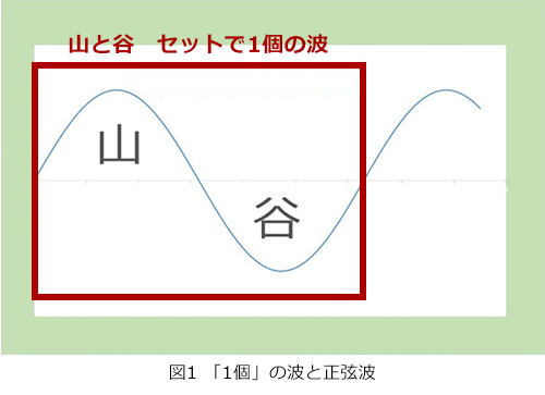
So what is a single wave?
A wave is a set of peaks and valleys that undulate. The combination of one mountain and one wave is counted as "one wave" (Fig. 1). A wave with the shape shown in Fig. 1 is called a "sine wave" and is the most basic wave. I'm sure you've heard the sounds of "sine, cosine, tangent." By the way, the cosine = cos is half the mountain = 1/4 of the wave, and is called "cosine" in Japanese (tangent = tan is Sin/Cos, but it's a little confusing, so I'll leave it out. increase).
And the frequency is how many times this wave appears in one second. One per second means Hz, 1000 means KHz = kilohertz, million means MHz = megahertz. When GHz = gigahertz, this wave will appear 10^9 = 1 billion pieces per second.
Digital signal and data rate
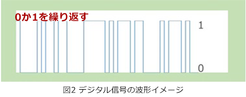
A digital signal is made up of 0s or 1s, like "0111100011010101...". An image of the “waveform” of the signal is shown in Figure 2. How many 0s or 1s appear in one second is called the "data rate", and is expressed as bps = bits per second = bits divided by seconds. As with frequency, the unit is promoted as it increases from K→M→G. Regardless of whether it is 0 or 1, 1.0 Gbps means that either one appears 1 billion times per second in total.
A signal has a frequency component. In other words, this digital signal is also made up of many "overlapping waves".
(1) Nyquist frequency
Then, when sending this digital signal by electricity, what state is electrically "busiest"?
Please recognize that "busy = intense movement". Then, the state where 0 and 1 are exchanged every time and come out continuously is the busiest. It's a little bit of a jump, but think of it as "having the highest frequency" when you're "busiest." Since it is a story, there is almost no mistake in this idea).
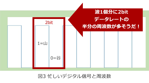
As explained at the beginning, one wave is a set of peaks and valleys. Looking at this busy digital signal, 1's are peaks and 0's are troughs. Since 1 and 0 are equivalent to 2 bits, you will intuitively notice that the frequency half of the data rate (frequency of occurrence of bits) seems to be strong (Fig. 3).
The half frequency of this data rate (1.0 GHz for 2.0 Gbps) is called the Nyquist frequency, which is the strongest component in digital transmission and the "highest frequency" as the "fundamental frequency". . By the way, this Nyquist is named after Harry Nyquist, who discovered the digital sampling theorem*, so it may be useful to know it as trivia.
*In order to sample an analog signal, it is necessary to sample at least twice as often as its frequency. Strictly speaking, the "Nyquist frequency" is also defined as the "maximum frequency" that can be expressed by the sampling frequency = Data Rate.
Now, I wrote "the highest frequency" as the "fundamental frequency" above, but it also includes higher frequency components. Digital waveforms are angular and snappy compared to gently rounded sine waveforms. To get that shape, it must contain high frequency components called "harmonics". It gets a little more difficult, but we'll cover that in the next section.
(2) Square wave/rectangular wave and harmonics
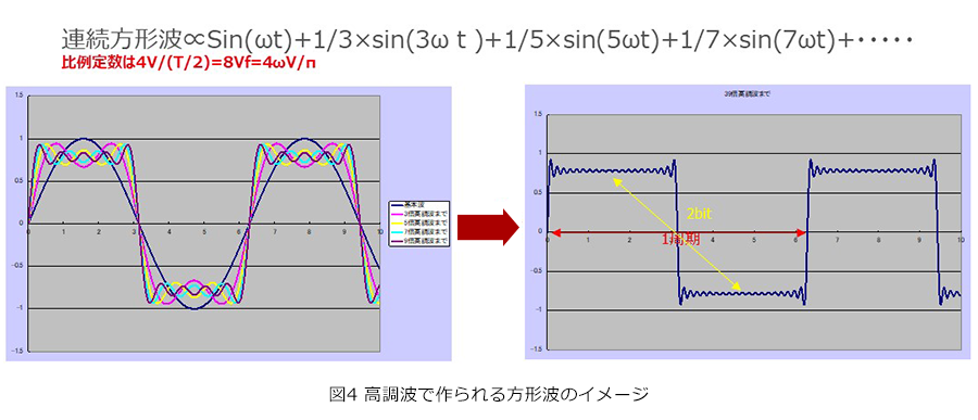
As many of you who are involved in music know, the "sound" of a sine wave is a clear, yet somewhat unsatisfactory sound, like a time signal called "pawn♪". Overtones or harmonics, which are several times the frequency of the time signal, are superimposed and blended in a well-balanced manner to produce a rich sound from musical instruments. The same is true for electrical signals. To achieve a square waveform, the "fundamental frequency" is the main component, and several sine waves of integral multiples of it must be overlapped at a "fixed rate". This is called a Fourier series, but here it is difficult, so I will focus on the result.
"To be square" means that a sine wave with a frequency three times the fundamental is 1/3 the magnitude of the fundamental, 5 times the magnitude is 1/5, and 7 times the magnitude is 1/7. , the ratio becomes smaller, but the components of "odd-numbered multiples of the fundamental frequency" continue to overlap (Fig. 4). It is these harmonics that form the “squishy” shape of the digital signal. In particular, it is related to the agility when the signal rises = 0 to 1 (and vice versa). However, as a matter of fact, the maintenance of harmonics has become a "give up" due to the recent increase in signal speed, and the movement to maintain transmission quality by securing transmission characteristics up to about Nyquist + α is becoming mainstream. increase.
Now that we've explained about frequencies that are "higher" than the fundamental frequency, let's talk about frequencies that are "slower".
(3) When 0 or 1 continues for a while and low frequency components
So far, we have discussed the Nyquist frequency, which is the fundamental frequency of a digital signal, and the "harmonic" components of the Nyquist frequency that result in square/rectangular waves as higher frequencies. So what about frequencies slower than the Nyquist frequency?
busy or not
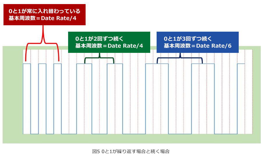
Actual digital signals do not repeat 0 and 1 alternately all the time, and 0 and 1 may continue for a while. So it's not crunchy busy all the time, and sometimes the signal slows down a bit. Let's take an extreme example, but let's look at a pattern where alternating 0's and 1's alternate all the time, followed by 2, 3, and so on, respectively, turning into a repeating pattern (Figure 5). As you can intuitively understand, the main components are 1/2 and 1/3 of Nyquist, respectively. If there are more 0s or 1s, the main component will be lower frequency. Also, since these "less busy" signals are also square/rectangular waves, they also contain a percentage of "harmonics above 1/2 and 1/3 of Nyquist". It's getting a little complicated, but a digital signal consists of a collection of frequencies of various components from low to high, centered on the Nyquist frequency. I will talk about that at the end.
④ Random signal and spectrum
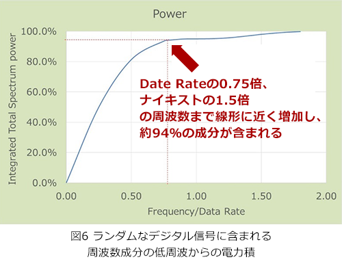
There are some examples of analyzing the frequency components of random digital signals on the Web. According to them, the integration of the power spectrum from low frequency to high frequency seems to be roughly as follows. Looking at this, we can see that the frequency components are stacked up from near DC and are distributed to a place much higher than the Nyquist frequency. So it is necessary to consider both the contribution of transmission quality to this wide range and the perspective of EMC.
At the end
Demands for high-speed transmission support for our product "connector" and Other components that form transmission lines are increasing year by year. For example, if it is a wireless connection that passes modulated signals (coaxial connectors are used), excellent = stable performance in "narrow band" of "very high frequency" which is the frequency of the carrier wave You are required to have In short, frequency requirements are pinpointed (although they cover a wider range as they are used for multiple apps).
On the other hand, connectors used in cases where digital signals are directly transmitted do not require performance at frequencies as high as the coaxial connectors mentioned above (assuming the same data rate), but they do require stable performance from low to high frequencies. IRISO' high-speed transmission products are developed with this in mind, and with a sincere commitment. Here you can find information on our various efforts in High-speed transmission Connector.
In addition, as the second part of this article, we have prepared "Frequency Distortion and Coding", which is more in-depth. Please take a look.