
- Top
- Technical Info
- column
- Frequency distortion and coding
Frequency distortion and coding
The technical note "Frequency and Data Rate" is the first part, and this time we will talk about "Frequency Distortion and Coding" as a sequel. If you have not read "Frequency and Data Rate", please refer to it first. It may be a little more difficult than the last time, but it is a simple summary of the contents that can be understood from the perspective of a connector manufacturer, so to speak, and the necessary range. It is compiled for non-specialists, and it may not be chewy for those who handle it professionally. Still, I would be happy if there were even a few people who could enjoy it as one aspect.
About 8b10b
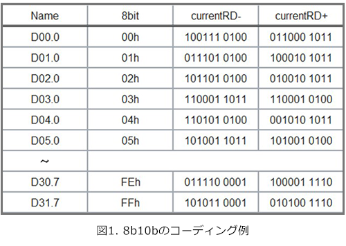
Coding 8b10b
8b10b is a coding invention invented by IBM in the early 1980s, sometimes referred to as 10b8b. Since it is a method of sending 8-bit "data" with 10-bit "data length", the efficiency is 80% = 20% "extra". By having this surplus, it is possible to understand the division (head) of 8 bits (bytes, octets) from a list of one continuous signal. So you sent the clock when returning serial transmission to parallel? In order to express it efficiently, I developed the coding shown in Fig. 1, but honestly, I'm one of those people who get a headache when I see this kind of thing.
Higher efficiency than 8b10b
Recently, coding such as 64b66b, 64b67b and 128b130b has been developed because "this 20% loss is a waste". For example, 64b66b is a coding that sends 64bit data with 66bit data length (about 97% efficiency). Both methods result in a much lower "redundancy" than 8b10b.
The reason why 8b10b is still useful "low frequency limitation"
Still, 8b10b is still prized. One reason for this is that as a side effect of this coding, 0s and 1s don't last very long (up to 4). In the "Frequency and Data Rate" article, "Data rate and frequency ③ When 0 or 1 continues for a while and low frequency components", it was briefly explained, but continuous 0 and 1 = "lower frequency components" so as not to be busy contains ". In other words, 8b10b cuts the low frequencies more quickly than a simple random signal, and is very gentle on "signal transmission through transmission lines."
However, I know some of you may be wondering, "I understand that high frequencies are difficult, but why should there be no low frequencies?" I would like to move.
Frequency distortion of transmission characteristics and square wave/rectangular wave
Frequency distortion received from transmission line
When an electrical signal is sent to the other side through a transmission line
① Smaller size
② It takes a long time to arrive.
Two phenomena occur. It takes time to transport all things, and it consumes energy, so I think it's relatively easy to understand.
① is called Insertion Loss, ② is called Propagation Delay, etc. The trends of these two characteristics change depending on the frequency (Fig. 2).
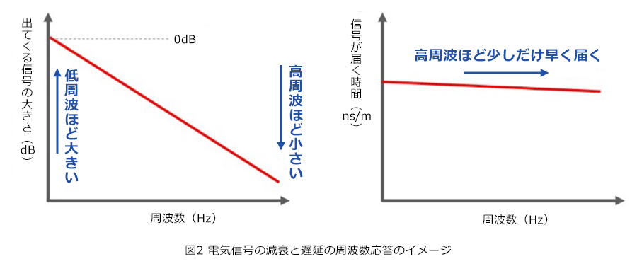
The higher the frequency, the greater the attenuation. In other words, the signal loses more and more energy and becomes smaller. This is caused by the skin effect of conductors, the dielectric loss of insulators, and the effects of a phenomenon called reflection. This is one of the reasons why high frequencies are said to be more difficult to transmit. On the other hand, the delay time also becomes "slightly" shorter as the frequency increases, and in fact it asymptotically approaches the original value. This is mainly caused by the phenomenon of reduction in inductance in the conductor due to the skin effect. This is the frequency distortion that the signal receives from the transmission line.
How does the signal waveform change?
So, let's see how the square wave/rectangular wave is affected after it propagates through the transmission line (Fig. 3).
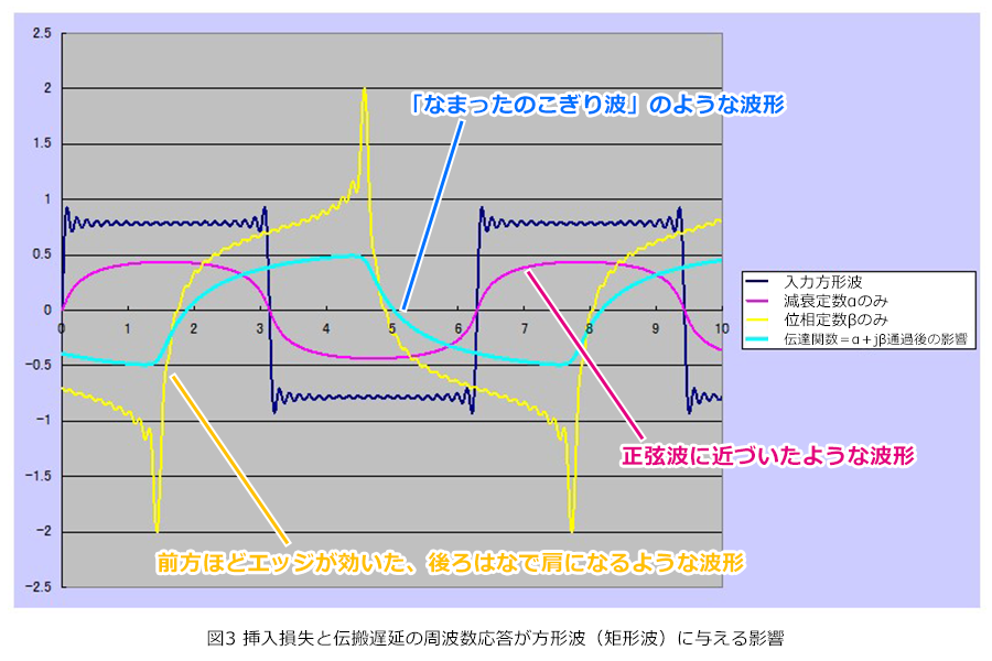
I think that many people have seen a light blue line waveform that looks like a "dulled sawtooth wave", which looks like a protrusion on the back of a dinosaur. This waveform is the sum of the effects of both insertion loss and propagation delay. As explained in "Data rate and frequency (2) Square wave/rectangular wave and harmonics" in the "Frequency and data rate" section, square/rectangular waves are made up of overlapping sine waves, the fundamental frequency and harmonics. .
First of all, due to the effect of insertion loss, the harmonics, which are higher in frequency, become much smaller, so the characteristics of the sine wave of the fundamental frequency, which is the base, become stronger, and the waveform becomes softer = closer to a sine wave (pink). colour).
On the other hand, due to the characteristics of propagation delay, the higher the harmonic, the more it rushes forward, so it takes on characteristics such as the yellow waveform, which has an edge in the front and a sloping shoulder in the back. By the way, this delay difference between the fundamental frequency and harmonics is called group delay.
These two effects combine to give the final output waveform a “dulled sawtooth wave,” similar to the aforementioned light blue color.
summary
"The size decreases and then delays", but if the degree is constant with respect to the frequency, all components decrease uniformly and delay, so the "square remains a square" only decreases. The distortion in such a dull waveform is a phenomenon that occurs because the transmission characteristics have a difference with respect to the frequency, which is distorted. And this dulled waveform is quite troublesome as a digital transmission signal that "determines 0 and 1 at each timing" depending on the degree. In addition, I will explain in the next section why not having too many 0s and 1s in a row is advantageous for transmission over a transmission line.
"Eye pattern", "Continuing 0 or 1" and "Decision threshold"
What is an eye pattern?
As many of you may know, there is a transmission quality confirmation method called "eye pattern". This is a visualization of the margin for judging 0 or 1 at each timing. The digital signal of random or actual transmitted and received data is represented by "overwriting" at each bit division (Fig. 4).
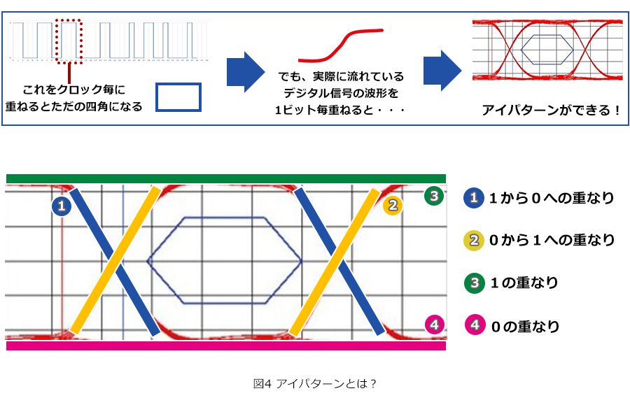
Fig. 5 shows the eye pattern and the allowance for judgment. Keeping your eyes wide open here is a guideline for sound data transmission. Now let's talk about the signal quality seen in the eye pattern.
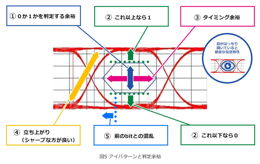
Signal quality seen in eye pattern = vertical direction
First of all, from the vertical "opening". Judgment of 0 or 1 is done by voltage. Depending on the performance of the receiving side, there is a "threshold" value for this judgment = threshold/threshold voltage. Since the judgment becomes ambiguous in subtle points, a "margin" is necessary for the judgment (Fig. 5 (1)).
The received signal must exceed the margin and be reliably judged as 0 or 1 depending on whether it is above or below (Fig. 5 ②).
Signal quality seen in eye pattern = lateral direction
On the other hand, in the horizontal direction, when it comes to timing, "when (what) signal is what is judged as 0 or 1", it cannot be established as a signal unless it is correctly recognized. Therefore, in order to avoid confusion, it is necessary to have some margin in the ambiguous part in the timing direction as well, such as "no signal is applied" and "bit change is not included" (Fig. 5 (3)).
Therefore, it is better to have a sharp rise at the transition point of the signal (Figure 5 ④). I think that you can get a vague sense that it is likely to cause "confusion" (Fig. 5 (5)).
If 0 or 1 continues for a long time.../8b10b is gentle on the transmission path
Next, we will finally move on to the question, "Why is it advantageous for transmission over a transmission line to not have too many consecutive 0s and 1s?"
Figure 6 shows what kind of waveform is output when a random signal is passed through a transmission line with typical characteristics as explained in the previous section, and what happens when it is converted into an eye pattern. .
What I want you to feel here is
① The waveform fluctuates up and down for some reason
(2) This fluctuation eats up the judgment margin both vertically and horizontally
③ Behavior is different when 0 or 1 continues and when repeated
That's the point.
As explained in "Data rate and frequency ③ When 0 or 1 continues for a while and low frequency components" in the "Frequency and data rate" section, when you are busy moving, the high frequency and the same signal continue If it is loose, the main component will move to the low frequency side. As mentioned in the previous section, in a typical transmission line, this phenomenon occurs because the signal output decreases as it goes to the high frequency side.
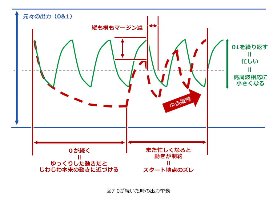
As shown in the image in Fig. 7, the busy switching signal is suppressed and reduced accordingly, but "low frequency = slow movement = not so small", so if 0 or 1 continues, it will gradually It approaches the "original output value". This is actually a problem because when you try to get busy again, your movement will be constrained, but the "starting point" at that time is not a simple repeating signal. This causes vertical fluctuation, and as a result, the vertical and horizontal judgment margins are “eaten”. Naturally, this phenomenon becomes more pronounced the longer 0s and 1s last, so 8b10b coding, which does not have many 0s and 1s, is very friendly to "transmission over the transmission line".
Now, I would like to talk a little bit about equalizing and pre-emphasis and de-emphasis for this frequency distortion.
Equalizing and pre-emphasis & de-emphasis
About the equalizer
The image of an equalizer is shown in Fig. 8, but simply put, "if there is frequency distortion, it should be corrected with something that is close to the opposite characteristics."
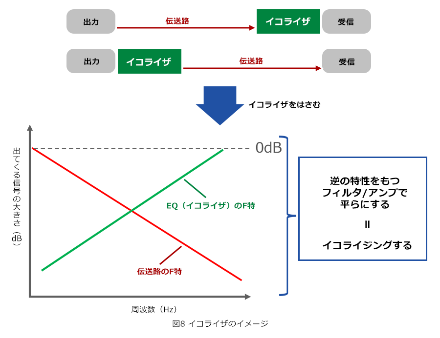
Basically, it is a high-pass filter, and there are passive = passive circuit type (cutting low frequency) and active = active circuit type (lifting high frequency / cutting low frequency). With these, it is possible to transmit signals that cannot be achieved with only ordinary 01 square wave/rectangular wave signals because the eye pattern is "collapsed". Some use preset patterns, but others, such as DFE (decision feedback) equalizers, tune between signal transmissions according to the actual situation, and are inseparable from high-speed transmission. has become
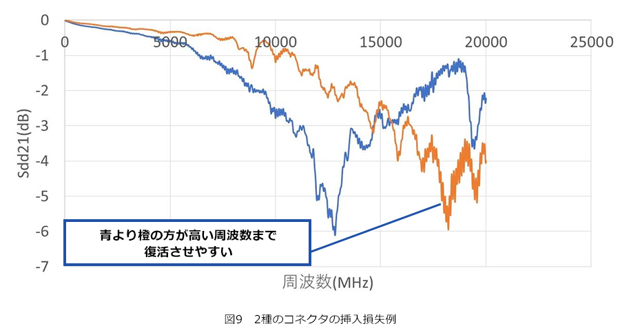
As a connector maker, the point we should be concerned about is that we can get help in reducing the signal degradation "obediently to the frequency". For example, in the insertion loss of the two types of connectors shown in Fig. 9, the blue line shows an unsatisfactory large drop when viewed against frequency near 12 GHZ, and then recovers again. In that respect, the orange line connector seems to be able to use higher frequencies even with the help of an equalizer.
Pre-emphasis and de-emphasis
Another method of dealing with frequency distortion in transmission lines is called pre-emphasis/de-emphasis/de-emphasis. You may have imagined that when you are busy moving = high frequency, but the fact that the higher the frequency, the smaller the signal, means that the more you try to move quickly, the more you will be suppressed = you will not be able to change completely at the point of change. will be roughly synonymous. Therefore, when there is movement (i.e., when there is a change), the original signal is changed excessively to penetrate through, and pre-emphasis is achieved by saying, "It will make sense when that part is suppressed!" (Fig. Ten).
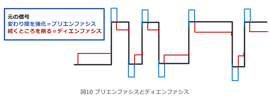
De-emphasis is almost the same, but this is aimed at relatively the same effect as pre-emphasis by cutting down areas that are not busy (i.e., areas where the same voltage continues). Even if the signal becomes smaller than the original, the eye will rather open after deterioration, as is the case with passive equalizers.
I think that if you imagine it in your head together with around Fig. 7 in the previous section, you will feel "Ah, it seems to be effective."
I first heard the term pre-emphasis about 20 years ago when I was in a different industry not far from where I am now. At that time, my first impression was that it was a much rougher method than equalizing, even though I was an amateur. However, after all, it is an amateur's impression, and it is actually very rational and has a great effect, and it is widely used now. Next, I would like to talk a little about what is called PAM-4.
About PAM-4
In general, digital signals are made up of 0s and 1s, and judging them by High or Low is a simple and more reliable method of information transmission. On the other hand, there is a method that we are hearing more and more these days, PAM-4. The waveform shown in Fig. 11 is obtained by stacking 2 bits vertically instead of two stages of 0 and 1 and transmitting signals in four stages of 00, 01, 10, and 11. By the way, there are special examples such as PAM-16, in which 4 bits are arranged vertically, and PAM-5, which adds a clock to 2 bits when sending GbEither over 4 pairs of UTP (unshielded twisted pair cables).
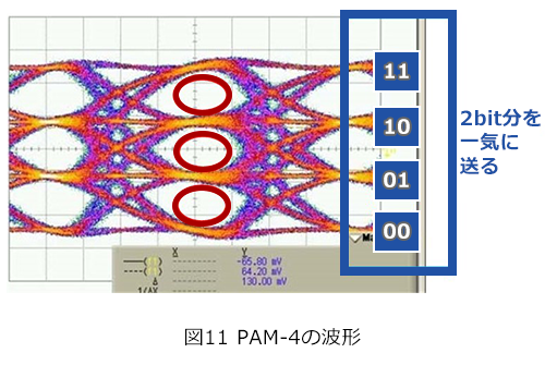
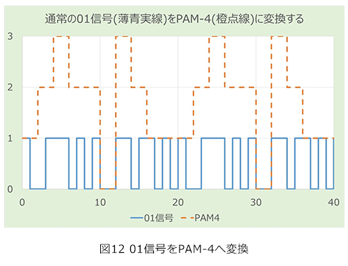
Figure 12 shows a simple 01 signal (blue) converted to PAM-4 format (orange). In the first place, I think that there are many people who can imagine 2 bits at once, but if you look at the fluctuations of the blue and orange waveforms, you will feel that the blue is moving more busily. One of the features of PAM4 is that the fundamental frequency component can be halved, and the lowering of the band of concern should be welcomed from both the EMC point of view and the transmission path. On the other hand, the movement in the vertical direction is slightly more complicated as the movement is relaxed.
If you look at Figure 11 again, you can see that there are now three thresholds instead of the usual one. As you read in the two previous sections, "'Eye pattern', 'The fact that 0 or 1 continues', and 'Decision threshold (threshold)', securing a margin for the threshold is a vertical line. I think that you can have an image that this is a little more difficult than usual because it has to be realized in three bullets. In other words, the frequency itself that should be a concern becomes lower, but while it is lowered, the transmission accuracy at that time becomes more severe. The same applies to frequency distortion and variations in the products that make up the transmission line. Even if the frequency is lower than that of normal signal transmission, each variation and instability at that point must be much smaller. It will be. As a result, the performance required for the connector is the same as for high-speed transmission, but the "point" to be evaluated is slightly different.
At the end
The topics I've covered in this article only scratch the surface of high-speed transmission. For example, even if a connector is used at the same speed (XX Gbps), the actual requirements and level may vary slightly depending on the specifics.
At IRISO, we have now clarified our own definitions and published representative recommended compatible data rates. We are then working to propose optimal products while carefully examining how our customers use the technology. As a connector manufacturer at the edge of high-speed transmission, we know that if we don't remain vigilant, we will quickly be left behind. We work hard every day to improve ourselves, and we are happy to be able to support the latest technology in our supportive work!
Here you can find our various initiatives for high-High-speed transmission Connector. Please take a look.
reference
We introduce representative recommended data rates that we have announced.