
FPC / FFC Connectors types and featuresFPC /FFC connector
- Top
- Technical Info
- What is a connector
- Types and features of FPC / FFC Connectors
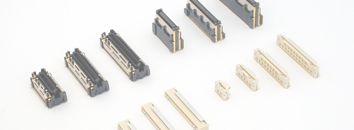
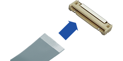
What is FPC / FFC Connectors?
As its name suggests, it is a connector made for the purpose of connecting FPC / FFC. Connect the Mating part to the FPC/FFC that is arranged on the terminal. This connector-Mating FPC/FFC is also called a card.
The pitch started at around 2.0mm, but gradually smaller ones became mainstream, and now the 0.5mm pitch is the most used. Also, the terminals are usually arranged in a row, but there are also ones with connections arranged in a staggered manner, mainly on smaller pitches.
We offer two types of connectors: a ZIF connector that can lock FPC/FFC with almost no force, and a NON-ZIF connector that can be inserted with light force.
ZIF and NON-ZIF connectors
ZIF connector
ZIF is an abbreviation for Zero Insertion Force, and refers to a connector that has zero insertion force, that is, no force is applied when mating the FPC/FFC to the Mating. On the other hand, the terminals must have contact pressure at the Mating part of the connector and the card, and it is also necessary to hold the card.
The ZIF connector has a locking mechanism for that purpose. There are mainly three types of locking mechanisms, called slider cover type, front flip type, and back flip type.
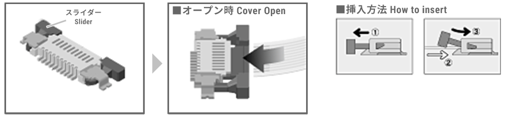
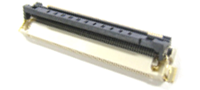
slider cover type
After inserting the card into the connector, a part called a slider cover pushes down the card together with the terminals, and has a locking mechanism that maintains contact pressure and card retention. It has been used from the beginning among the three types of locking methods. While it has high card holding power, it is disadvantageous in terms of size and workability.
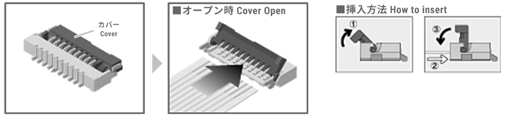
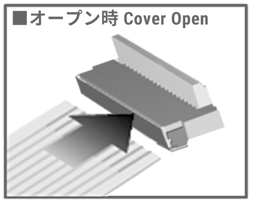
Front flip type
Compared to the slider cover type, this type has improved workability and size disadvantages. By occupying the cover that falls to the card side, it has a mechanism to hold down the card. As mentioned above, it has superiority in terms of size and workability, and is now being used more than the slider cover type. On the other hand, there are issues with the holding power when the card is tilted upwards, and if a strong holding power is required, it may be avoided.
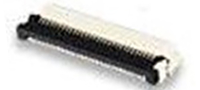
Back flip type
It is a type that knocks down the lever behind when viewed from the card insertion side. Compared to the front flip type, it is more resistant to card tilt and tends to have better holding power.
On the other hand, there are cases where the connector size tends to increase in the depth direction, it is disadvantageous for inspection of the SMT mounting part because the terminal is hidden, and additional measures such as making the mounting part long tail are required. I have.
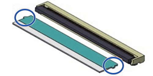
Optional lock for ZIF connector I-Lock mechanism
The figure shows an example of combination with a slider cover type, in which a notch is made in the resin part of the card, and the notch is made to climb over the holding terminal on the spring to provide a temporary holding function.
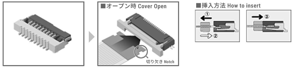
In order to avoid incomplete Mating, this mechanism is called a "latch feeling," which allows the user to perceive that the card has been inserted in the correct position, and maintains this position until the lock is applied. As for positioning, there is also a specification in which protrusions are attached to both sides of the card, and dents are made in the resin part of the connector body and fitted in there.
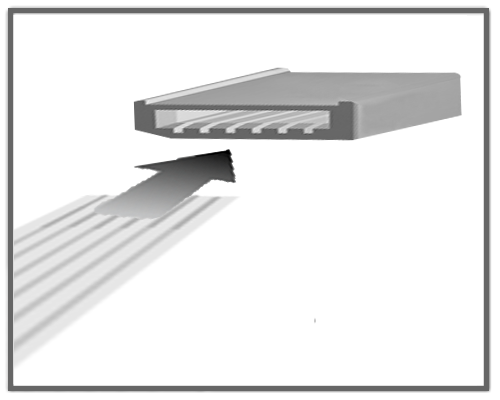
Non-ZIF connector
It is not a ZIF, that is, a connector that requires force (insertion force) when Mating the card into the connector. Focusing on those with relatively low insertion force, it also includes what is called LIF (Low Insertion Force).
This type does not have a locking mechanism as explained for the ZIF connector, but instead the terminals are arranged to have contact pressure from the beginning, which is a simple connector that also serves as a card holder. Therefore, it is superior in terms of workability and size, and it is easy to keep costs down.
On the other hand, there are disadvantages such as a weaker retention force especially when there are few poles (a small Pin Counts), and conversely, a higher insertion force is required when increasing the number of poles, which can be straining.
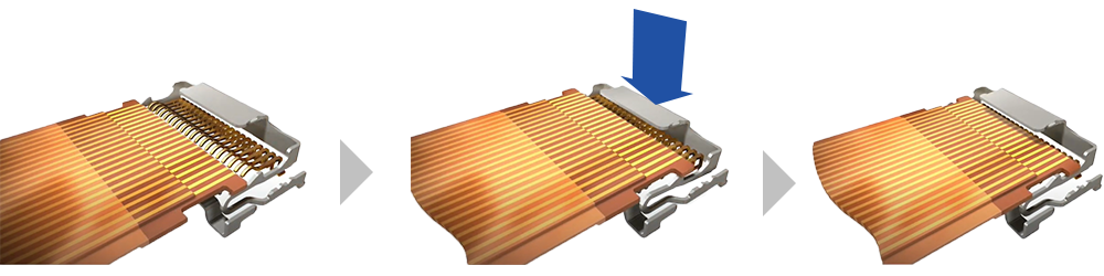
New FPC / FFC Connectors Auto I-Lock structure developed from non-ZIF connector
This is a completely new concept product realized by further developing the I-Lock, which was an optional mechanism of the ZIF connector mentioned above, and combining it with the Non-ZIF structure. While retaining the good workability that was the advantage of non-ZIF connectors, this connector realizes card retention and complete insertion perception. Not only is it compatible with various types of automation, but it is also highly compatible with manual work, and troubles caused by incomplete insertion. etc.
Proper use of each connector type
Summarize the features, advantages and disadvantages of each FPC / FFC Connectors.
| type | Workability | card insertion force | card holding power | size and cost | ||
|---|---|---|---|---|---|---|
| ZIF | Slider | 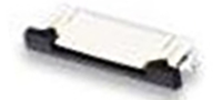 |
 2 actions Work with both hands required *1 lock is heavy |
 |
 |
 easy to grow, Higher than Non-ZIF |
| front flip |
 |
2 actions Work with both hands required *1 |
|
Miniaturized as a ZIF Easy to reduce cost |
||
| back flip |
 |
2 actions Work with both hands required *1 |
|
It tends to be longer in the depth direction *2 Higher than Non-ZIF |
||
| Non-ZIF |  |
1 action, but correctly Hard to tell if Mating |
|
|
Both cost and size advantageous |
|
| Auto I-Lock structure |  |
1 action and auto lock Good for both manual and Robot assembly |
|
|
slightly larger, Higher cost |
|
*1 Can be improved with I-Lock
*2 Visual inspection of SMT requires long tail
The above is a general guideline, and the actual results will depend on the detailed specifications. In addition, each product has different characteristics depending on the environment in which it will be used, and customers will need to select the product based on Pin Counts, temperature, and electrical rating required.
An example of our proposal
- ・When used to connect parts where tension is applied
Holding strength is key.
slider cover type is recommended. At the same time, please consider Auto I-Lock structure. (Assuming a Floating part or a part where the card is mounted while being pulled upward)
- ・When the card is fixed and the connection is not subject to vibration, and the work is done by a person.
Cost and workability of card Mating workers are the keys.
Front flip type and Auto I-Lock structure are recommended. Auto I-Lock structure is especially recommended from the standpoint of operator perception of Mating.
- - When automating card insertion
Auto I-Lock structure is recommended.
We will make a proposal according to the customer's request. Please contact our sales staff or contact us using the inquiry form.
IRISO FPC/FFC Connectors
Here we introduce typical types of our FPC / FFC Connectors. Click here for the product list.
slider cover type
9686S series

0.5mm pitch, SMT, RA (bottom contact) type FPC/FFC connector. IRISO unique locking system, I-Lock, prevents FPC/FFC cards from slipping out. A definite click is felt when inserting the FPC. Improved workability and quality.
9664S series
1.0mm pitch, SMT, RA (bottom contact) type FPC/FFC connector. IRISO unique locking system, I-Lock, prevents FPC/FFC cards from slipping out. A definite click is felt when inserting the FPC. Improved workability and quality.
Front flip type
12001S series

0.5mm pitch, SMT, RA (bottom contact) type FPC/FFC connector. IRISO unique I-Lock locking system thoroughly prevents FPC/FFC cards from coming loose. Front flip structure for easy operation. Highly reliable 2-Point Contact. 125°C specification also available to withstand the high temperatures of automotive equipment.
9637S series

0.5mm pitch, SMT, RA (bottom contact) type FPC / FFC Connectors. Flip lock type for ease of use. Workability is improved with a click feeling when the cover is locked. Equipped with a cover fixing function when the cover is opened.
Back flip type
9697S series
0.5mm pitch, SMT, RA (double-sided contact) type FPC/FFC connector. Ultra-low profile profile, space-saving type. Back-flip structure with good workability. FPC/FFC card removal prevention structure is adopted. Prevents card removal from FFC with high connection reliability.
Auto I-Lock structure
11600S series
This 0.5mm pitch NON-ZIF RA type FFC connector is compatible with shielded FFCs, enabling high-speed digital signal transmission. The shielding provides EMC protection. The optimized contact structure supports transmission speeds of over 20Gbps depending on the FFC selected (a representative reference value defined by the company). Impedance matching: differential 100Ω. Auto I-Lock structure makes it difficult to remove, yet easy to do so. It features a locking mechanism that locks the FFC card as soon as it is inserted. It also contributes to Assembly automation by being Robot Friendly connector.
11501S series

This 0.5mm pitch NON-ZIF RA type FFC connector is compatible with shielded FFCs, enabling high-speed digital signal transmission. The shielding provides EMC protection. The optimized contact structure supports transmission speeds of over 20.0Gbps depending on the FFC selected (a representative reference value defined by the company). Impedance matching: 100Ω differential. Auto I-Lock structure prevents disconnection yet makes removal easy. The FFC card is designed to lock in place as soon as it is inserted. It also contributes to Assembly automation by being Robot Friendly connector.
11503S series

This 0.5mm pitch NON-ZIF RA type FFC connector is compatible with shielded FFCs, enabling high-speed digital signal transmission. Its shielding provides EMC protection. The optimized contact structure supports transmission speeds of over 20Gbps depending on the FFC selected (typical reference value defined by the company). Impedance matching: 100Ω differential. Auto I-Lock structure ensures easy removal while remaining secure. It features a locking mechanism that locks the FFC card as soon as it is inserted. It also includes a confirmation window for visual inspection of complete FFC insertion. It also contributes to Assembly automation by being Robot Friendly connector.