
- Top
- Technical Info
- technical note
- Regarding definition of supported data rate of FPC / FFC Connectors
Regarding definition of supported data rate of FPC / FFC Connectors
Measurement using the reference FFC (length 100/200/300mm) defines the following two points
-
Definition ①:
-
-
Determined from the S parameter at differential 100Ω, the lowest value among the following is the (recommended) transmission speed/Data Rate
- Insertion loss = Sdd21 has sufficient linearity up to the Nyquist frequency
- Return loss = Sdd11/Sdd22
- Do not exceed -15dB up to the Nyquist frequency
- Do not exceed -10 dB up to 1.5 times the Nyquist frequency
-
-
Definition ②:
-
Satisfy the requirements by evaluating specific standards (However, Sdd21 is assumed to have sufficient linearity up to 1.5 times Nyquist)
Unless otherwise specified, the acquisition of S-parameters shall be obtained with those recommended in the product drawing, and shall include the mounting part (ex. pads on the substrate side for SMT, etc.)
(Additional to definition 2) If compatibility with or compliance with an interface standard, etc., is indicated, the requirements of that standard are met.
* Products without a GND must be grounded on the FPC/FFC side.
When defining the supported data rate of the FPC / FFC Connectors
To ensure consistency and avoid customer confusion, we have aligned our data rate definitions with those of Board to Board Connectors. For our basic thinking, please refer to "Definitions of supported data rates for Board to Board Connectors."
When defining the supported data rates for FPC/FFC connectors, the following differences were noted compared to Board to Board Connectors, and required adjustments.
- Performance largely depends on the specifications of the FPC/FFC used
- Performance depends on length
- Occupying a higher proportion of the entire transmission path in many cases/close to Chip to Chip
Taking the above into consideration, we have removed the absolute value standard from Sdd21 and established Definition ② for cases where compliance with various standards coincides with the compliance point (this also applies to some Board to Board Connectors by adding appropriate traces).
For examples of definition (2), please refer to "High-speed Transmission Solution" as well.
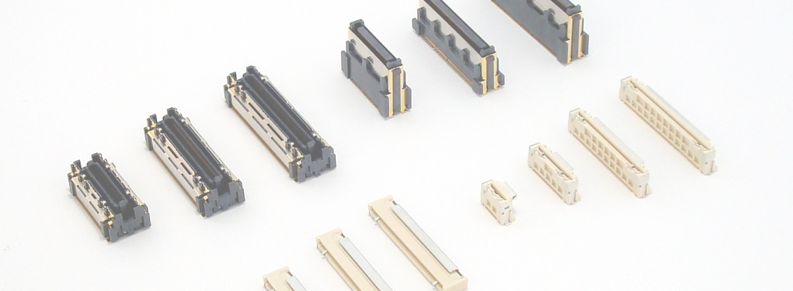
Supported data rate list for each product (recommended value)
Listed from those that have been evaluated/assessed (updated as necessary). In addition, it is implemented from the 0.5mm pitch connector.
| Product | Definition ① | Definition ② | ||
| product type | series | Data rate | Data rate | Target standard |
| Flip type 2-point contact | 12001S | 1.0Gbps | ― | ― |
| 12003S | 1.0Gbps | ― | ― | |
| slider cover 1-point contact | 9631S | 1.7Gbps | ― | ― |
| 9632S | 1.7Gbps | ― | ― | |
| 9685S | 1.7Gbps | ― | ― | |
| 9686S | 1.7Gbps | ― | ― | |
| Flip type 1-point contact | 9637S | 1.7Gbps | ― | ― |
| 9681S | 5.0Gbps | ― | ― | |
| Auto I-Lock structure | 11501S | 12.0Gbps | 25.0Gbps | CEI 28G-SR |
| 11503S | 12.0Gbps | 25.0Gbps | CEI 28G-SR | |
| 11600S | 12.0Gbps | 25.0Gbps | CEI 28G-SR | |
Regarding use at a supported data rate (recommended value) or higher
As mentioned above, the transmission characteristics of FPC / FFC Connectors are highly dependent on the wire used, and the speed that can be supported also changes depending on the customer's actual equipment design. Our company's definition (2) refers to the standard, but our own definition (1) is a relatively strict assessment value. If you are considering using a higher data rate, please consult your sales representative or contact us via the web. Depending on the content, we may be able to propose additional evaluations and recommended FPC/FFC specifications that are closer to your company's consideration.
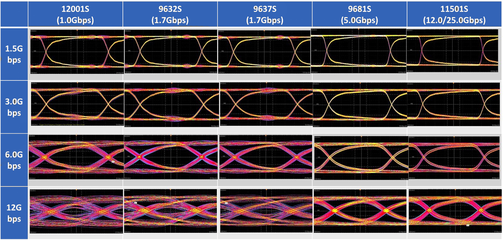
Below are reference waveforms for observing eye patterns up to 12Gbps (PBRS = 2^7-1, using a 300mm FFC). You can check the possibility of using each connector in areas that exceed the recommended data rate.
When using a product without a GND
Impedance matching FPC/FFC has a shield layer. It is necessary to implement grounding processing on the FPC/FFC side, or use an FPC, etc. with the shield dropped on a specific pin.