
- Top
- Technical Info
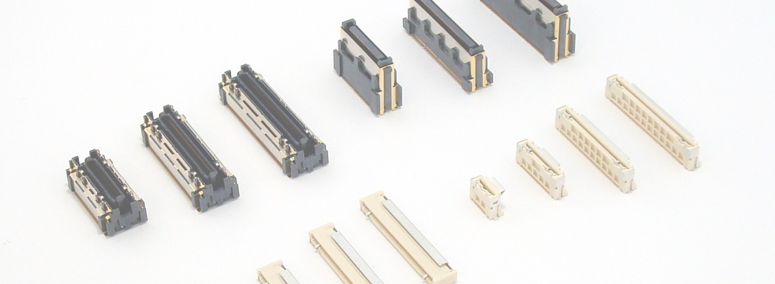
- What is a connector
- Options to improve connector reliability
2-point contact connector
What is a two-point contact?
Two-point (or multi-point) contacts are an option to improve connector connection reliability, and various structures have been devised. As the name suggests, it is a connector that has ``2'' contacts for one connection, and is a technology that realizes ``as long as either one is connected, it's OK'' = redundant connection. This reduces the risk of problems during Mating and momentary disconnections due to vibration. In addition, it is also possible to have the effect of removing foreign substances by meeting certain structural conditions. On the other hand, there are also weaknesses, or issues as a two-point contact point. We touched on this a little in "What is a connector?", but here we will explain it in more detail.
Main two-point contact structure
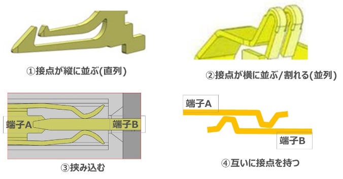
As mentioned above, various structures have been devised for two-point contacts and are on the market, but they can be roughly divided into four types.
(1) Vertically aligned contacts
(2) Contacts lined up horizontally = Broken object
(3) A structure in which the male contact (plug) is sandwiched between the female contact (Socket)
(4) Each has a contact point and each is combined to form a two-point contact point.
Various two-point (multi-point) contact structures can be said to be largely derived from these four.
for example coaxial connector, etc. can also be regarded as multi-point contacts in 360° rotation, but this can also be said to be a derivative of ③.
Conditions for Properly Providing Redundant Connections
In order to provide redundant connections, any of the four structures in the previous section must be "spring independent". The figure on the right is an example of a very simple diagram of a foreign object running on top of the contact. I'm here. This is not only due to interference with Mating due to foreign matter. For example, if the two contacts move synchronously due to momentary disconnection due to vibration, connection redundancy cannot be expected.
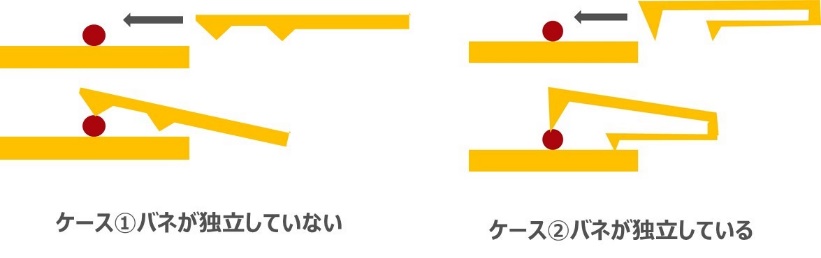
In terms of ① to ④ in the previous section, ③ and ④ would not be possible if the springs were not independent in the first place. On the other hand, if the springs in ① and ② are not independent, it may be possible to expect improved reliability in terms of, for example, the effectiveness when there is a local defect on the other side, or the wiping effect against soft foreign matter (①), or the discharge mechanism like the grooves in a tire (②), but independent springs are necessary to ensure an accurate redundant connection. As a rule, all two-point contacts provided by IRISO have independent springs.
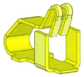
For example, although not many others offer this type Compression Terminal, we also offer a type with two independent spring contact points.
Series 2-point contact effective for foreign matter removal
This content overlaps with "What is a Connector?". As you can see from the video below, the serial type two-point contact has the effect of wiping away foreign matter. This effect can only be expected with the serial type (1) of the categories (1-4) mentioned in the previous section. When adopting two-point contacts, IRISO places emphasis on this foreign matter removal effect, and primarily uses the serial type. In fact, this has contributed to improving Mating problems caused by foreign matter for many customers.
Issues with 2-point contacts: Compatibility with high-speed transmission
So, is two-point contact a panacea? It is true that there are some difficult aspects to it. This is the issue of compatibility with high-speed transmission. One issue is that the terminal shape becomes complex, making it difficult to ensure impedance matching (issue 1). For more details on this, please see IRISO technical note "Are 'Floating structure' and 'high-speed transmission' contradictory requirements?"
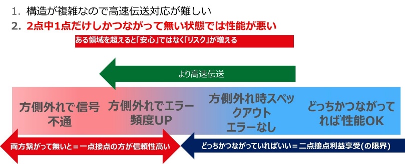
Another problem, which is more serious if it occurs, is that even if the initial characteristics are good, "performance will not be obtained if one side of the two-point contact comes off" (challenge 2). The contact on the detached side becomes a state called a "stub", where the high-frequency signal resonates, making it impossible to maintain sound transmission. Redundancy should have been ensured by having two points of contact, but if it goes beyond a certain area, it will actually "take on more risks".
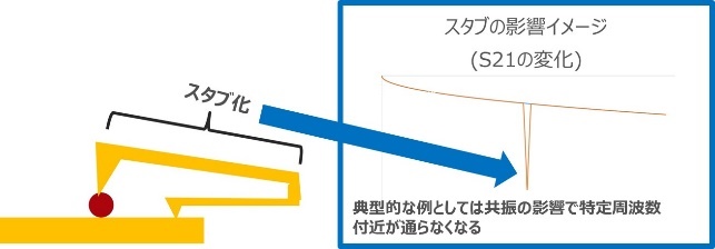
There is also the difficulty that this cannot be detected, for example, in a DC/low frequency signal inspection at the time of equipment start-up. Although it depends on the size of the connector and the specific design, these problems become noticeable, but there seems to be an example where they become apparent after exceeding 10 Gbps. Such phenomena on the high-frequency side are difficult to reproduce through actual verification, so risks can be reduced by performing advance verification such as confirming changes in performance when one side is detached by electromagnetic field simulation. On the other hand, if it is a "high-speed transmission" with a lower rate to some extent, we can expect improved reliability (Fig.). In the first place, a detailed design is necessary to bring the solution of issue (1) to this area, so it is also a problem that is currently manifesting only in limited places.
Currently, IRISO has not released any two-point contact connectors for applications where this problem becomes apparent (supporting 10Gbps or higher), but IRISO has not given up on future products that overcome all of these challenges.However, there are other ways to improve reliability besides two-point contact, so if you are looking to achieve both connection stability and high-speed transmission, please feel free to contact us first.
Electrostatic shield/ GND
What is an electrostatic shield?
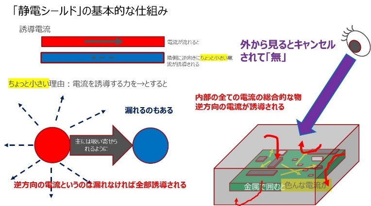
Roughly speaking, an electrostatic shield is a method of enclosing an object through which an electrical signal flows with a metallic body. When an electric current flows in a certain place, something called an induced current flows in the nearby metal (conductor) in the opposite direction to the current that caused it. The fact that an electric current is flowing means that an electromagnetic field is generated around the electric current. increase. Therefore, an electrostatic shield is a shield that surrounds an electronic device or part with a metal body to cancel out the electromagnetic field generated from inside, that is, noise. This has the same effect on noise coming in from outside. This includes metal housings of various devices and shields applied to electric wires, and shield products on bags that wrap them are also seen on the market.
Connector electrostatic shield
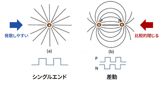
It is also used in connectors as a metal shell, which is attached to a variety of products. IRISO has also released a shielded Board to Board Connector connector. It is effective for differential transmission, but while it is relatively better in differential transmission because the electric field tends to close due to a phenomenon called "coupling" within the line, it is more effective in single-ended transmission, where the electric field tends to diverge.
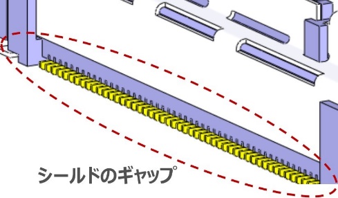
The problem of gaps in electrostatic shields
By the way, there is a problem that bothers us as a connector manufacturer. It's a question of how to manage shield gaps. Such in-machine connection type connectors inevitably have gaps in the shield, especially in SMT mounting, because they are mounted on the board. In particular, if you want to perform a visual inspection of soldering conditions (fillets, etc.) without using X-rays, etc., it is necessary to secure a large area. Leakage of the electromagnetic field occurs from this gap, and especially the shorter the wavelength, the higher the frequency, the narrower the gap, so the effectiveness of the electrostatic shield may be lost in the first place. In such a situation, it may be better to use the cost of shielding individual parts for other countermeasures (additional countermeasure parts, etc.). On the other hand, if it is combined with a connection form such as BGA or press-fit, this gap can be made smaller, and gimmicks that cover up even SMT types have been devised/commercialized. These options should be considered while matching with the actual customer's manufacturing process and expected cost. In addition, it is necessary to consider whether it is necessary to improve the EMC characteristics of the entire device, or whether it is necessary to take countermeasures against self-poisoning (including interference with wireless modules, etc.).
grand terminal
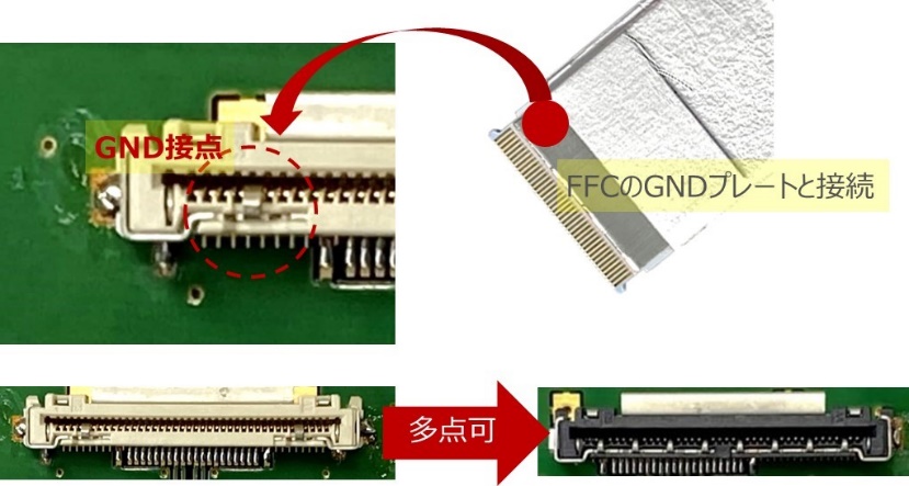
A ground terminal is a terminal for grounding/connecting an electrostatic shield, etc. The figure on the right is the terminal for grounding the electrostatic shield (tape) of the FFC to the board through the connector. As an option for this, there is a connector with the option of increasing the number of multi-point contacts = ground terminals (customized product). This reduces the ground resistance and is actually effective for some customers.
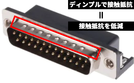
The dimple structure seen in the Mating part of the metal shell of the I/O cable (although it is not commercialized by our company) has the same purpose, and is applied for the purpose of reducing the ground resistance of the shield and increasing the shield effect. increase. In addition to the gap problem mentioned earlier, how to ground with low resistance is also a factor that determines the performance of the electrostatic shield.
Electrostatic shielding is an extremely effective and relatively inexpensive countermeasure in areas where it is expected to be effective. Because it is difficult to quantitatively evaluate the effectiveness of EMC and electrostatic shielding on individual components in a practical manner, IRISO combines methods such as electromagnetic field analysis and near field measurements to evaluate the effectiveness of individual components and accumulate know-how from customer feedback. We will continue our daily development to address the issues mentioned above and further improve the "improved reliability" that electrostatic shielding brings.