
- Top
- Technical Info
- column
- "Resistive loss" and "dielectric loss" signals change to heat and become smaller?
"Resistive loss" and "dielectric loss"
In the high-speed transmission area, why does the signal "attenuate = become smaller" when passing through a transmission line? This time, I will talk about the loss that depends on the material around the transmission line, which is the loss due to electrical resistance and the dielectric loss, among the attenuation of the signal.
With the recent spread of 5G and millimeter-wave signals, various materials and low-loss components that are called "compatible!" are attracting attention. It is thought that matching, design and development of connectors with such products will progress. So I hope I can give you a rough idea of the brief technical background of such products, why and what they are good at.
Why is the signal getting smaller?
When considering why the signal becomes smaller, the reasons fall into two families.
Reason ① Reflection loss
The first is a phenomenon called reflection or crosstalk, in which a signal goes in the wrong direction, or becomes a different signal. In particular, reflection loss is still dominant in connectors, and in our products that currently support high-speed transmissions up to 25 Gbps, controlling the characteristic impedance to reduce this is the biggest issue for high-speed support. Regarding that, please refer to another article on this page titled "Are 'Floating structure' and 'High-speed transmission' contradictory requirements?"], so please refer to it.
Reason ② Lost energy becomes heat
The second is a phenomenon in which the signal energy is converted into heat energy, resulting in a smaller signal.
this is,
・Heat generation depending on the electrical resistance of the conductor = resistive loss
・Phenomenon that is lost by heating the surrounding material (dielectric) = dielectric loss
can be considered in two parts. First, let's talk about resistive loss, which many people are probably familiar with.
About resistive loss
Resistive Loss: Ohm's Law
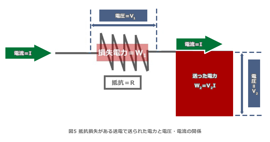
There is a theorem called "Ohm's Law" that I am sure you have heard in junior high school. When a current = I flows through an electrical resistance = R, a voltage is generated before and after it. And power = W is consumed in electrical resistance. Each relationship is based on Ohm's law and is shown in the figure below.
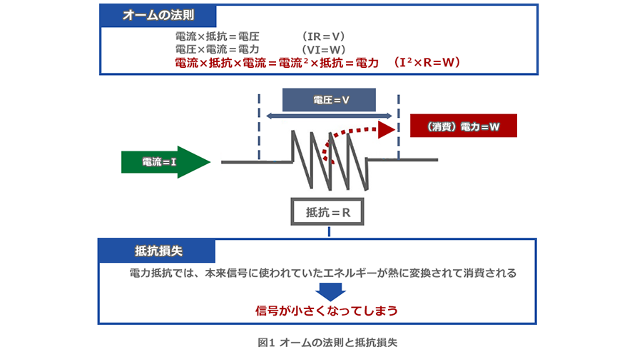
This consumed power is converted into another electrical energy. In the case of motors, it is converted into kinetic energy, and in the case of mini bulbs and lighting equipment, it is converted into light energy. This is converted into "heat" by electrical resistance. It is this phenomenon that the wire on the side of the plug inserted into the outlet becomes hot. Or, you may have played with short-circuiting both ends of a dry battery with a wire when you were a child, saying "It's hot!" . In this way, the energy originally used for the signal is converted into heat and consumed, resulting in a smaller signal.
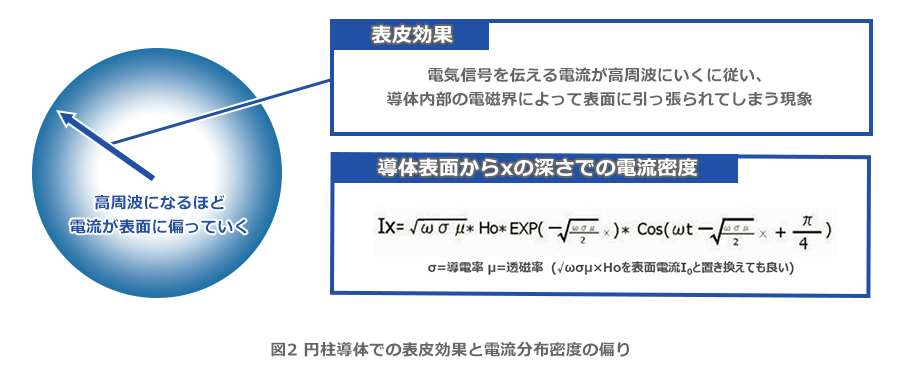
Phenomenon called skin effect
By the way, the higher the frequency, the smaller the electrical signal tends to be. I'm sure many engineers who work with signals have experienced this first-hand. One of the major factors is the increase in resistance due to the "skin effect" of conductors. The skin effect is a phenomenon in which the electric current that conveys an electrical signal is pulled to the surface by the electromagnetic field inside the conductor as it goes higher in frequency. By the way, I think it's going to be a trivia content, but if you're a science student, you've probably learned about it at university, so-called "ideal conductors", where the resistance value is zero, there is no electromagnetic field inside the conductor. So no skin effect occurs. In fact, in such cases, from the very beginning (the DC stage), the current only flows on the surface of the conductor. For this reason, I wrote earlier that "the electromagnetic field inside the conductor pulls it toward the surface," but it might be more correct to say that "the force that pulls it into the conductor becomes weaker." And if you put this phenomenon into a mathematical formula, it will be a slightly complicated formula as shown in the figure below. This is a little tricky...
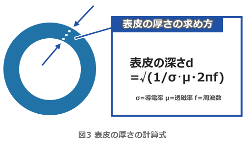
epidermis thickness
To capture the increase in resistance at high frequencies a little more easily, the definition is "skin thickness." This assumes a hollow ring model equivalently approximating a conductor in a state biased toward the surface of the current, and determines the thickness of the ring part. It becomes the image of Fig. 3.
I think it's a little clearer, but it's still a bit complicated. So, here are three points I would like you to take roughly.
(1) The skin becomes thinner and thinner in proportion to √f = the resistance value increases at high frequencies
② conductivity The higher the , the greater the degree of resistance, but since the specific resistance value is low in the first place, "go".
(3) The higher the magnetic permeability, the greater the degree = Magnetic metal tends to increase resistance at high frequencies
For reference, copper, which is often used as a conductor, has an approximate skin thickness of 2 μm at 1 GHz and 0.6 μm at 10 GHz. Recently, there are many calculation sites, so please try various calculations.
Conductor shape and material
Here, let's think a little about the shape and material of a conductor that "does not easily increase resistance at high frequencies."
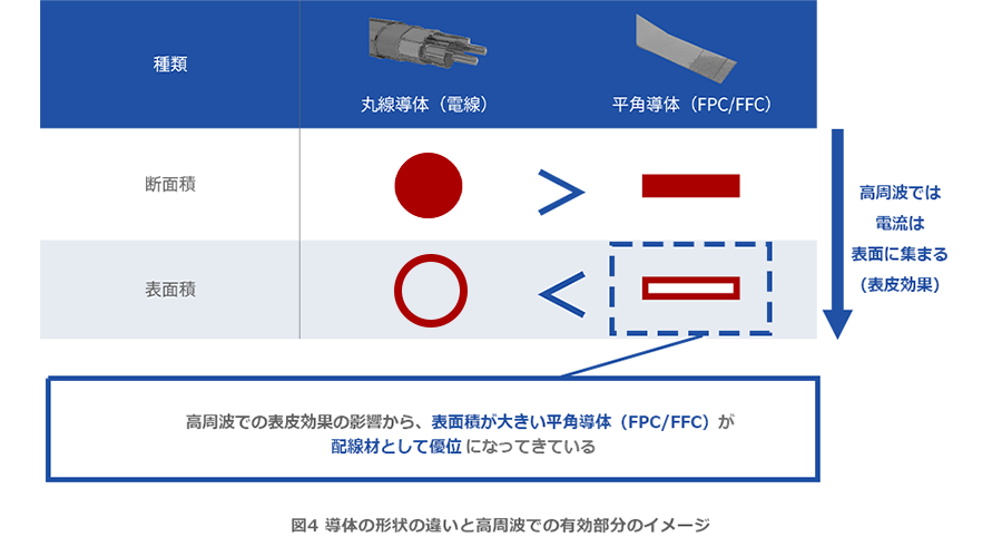
First from the shape. In general, many people understand that "a conductor with a large cross-sectional area = that is, a thicker conductor has a lower resistance value, and less heat is generated when current flows = less signal is less likely to decrease." I think so. If the shape is the same, the thicker the wire, the lower the resistance. This does not change even at high frequencies. On the other hand, as the current is biased toward the conductor surface due to the skin effect explained in the previous section, we are entering a region where a large surface area is more advantageous than a cross-sectional area. The image below is the image.
For a long time, so-called electric wires that use round wires that make it easier to secure a cross-sectional area have been advantageous for high High-speed Transmission Solution, but recently there have been cases where FPC/FFC, which make it easier to secure a conductor surface area, has an advantage. In this regard, we also touch on 25Gbps-compatible solutions that use FFC in "25Gbps-compatible Floating structure Board to Board Connector" in "High-Speed Transmission Solutions," so we hope you will take a look.
Nickel plating which is magnetic
In addition, with regard to "thickness of the skin," I summarized that "magnetic metals tend to increase resistance at high frequencies." Specifically, it is becoming difficult to handle nickel plating, etc. at high frequencies "in order from the long transmission line". Nickel plating has excellent corrosion resistance and is effective as a base plating for various types of plating. Even in connectors, the base for gold plating is nickel plating. In the case of partial gold plating, most of the outer layer is nickel, and at a fairly high frequency, current only flows through that area. In other words, we are entering an area where the base material is no longer relevant.
Fortunately, however, the size of the connectors we handle has not yet been a problem, and as I mentioned at the beginning, "control of characteristic impedance" is a battleground. On the other hand, in the future, when it becomes necessary for electrical connectors to withstand transmissions of several hundred Gbps to Tbps, we will apply low-resistance metal plating on the outermost surface or shift to plating such as non-magnetic nickel-phosphorus. We are proceeding with product development while keeping in mind that it is possible that the
Is it better to use less current for the same power? (high voltage lines, etc.)
I would like to talk about a slightly different point.
Because of the 100V power supply that is sent to household outlets, you may have seen or heard of "high-voltage wires" when you go outside. Power plants generate electricity at very high voltages of tens of thousands of volts. As it is, it is inconvenient and dangerous to use, so the voltage is dropped, but at the substation, it is only dropped up to 6600V. It is finally lowered to 100V by the transformer installed on the utility pole just before each home. 6600V seems to be still dangerous, safety measures will be costly, and accidents on transmission lines are still not zero. If so, some people may think that it would be better to drop it to 100V sooner. However, there is a solid reason why it must be sent at a relatively high voltage. This is because if you want to send the same power, you have to send "larger current" with "lower voltage". Ohm's law W (power) = V (voltage) x I (current) again. The greater the current, the greater the energy lost during transmission.
See the diagram below. Starting with transmission lines, the wires that supply power to all kinds of equipment, as well as the traces on boards, have "electrical resistance." The energy lost there is R×I2 as explained in the item of resistive loss. In other words, the less current the less energy is lost.
Among the electrification, especially in Europe, there was a trend to change the battery voltage of hybrid vehicles from 12V to 48V. This also reflects this content (although it seems that a higher voltage is better, 48V seems to have a better balance due to issues related to safety standards such as wires and usability).
Now let me explain a little bit how this works in the high frequency world.
Current flowing through the transmission line = Characteristic impedance
In the world of high frequencies and high-speed transmission, the balance between current and voltage flowing through a line is determined by the structure and material of the line. The ratio at this time, voltage/current, is a parameter called characteristic impedance. For a little more detail, please refer to "Are 'Floating structure' and 'high-speed transmission' contradictory requirements?" When trying to send the same signal energy, the higher the characteristic impedance, the smaller the current value that flows. In other words, is it possible to reduce the resistance loss by increasing the characteristic impedance as much as possible? To put it a little cumbersome, this is slightly correct, but largely wrong. The slightly correct answer is correct if you have conductors with the same resistance value. However, if you try to increase the characteristic impedance, you will need a "larger space" if you have the same conductor. To put it the other way around, if you want to have a "larger conductor = lower resistance conductor = lower loss" in a limited space, you have to steadily lower the characteristic impedance.
This is also explained in the previous section, "Are 'Floating structure' and 'high-speed transmission' contradictory requirements?"
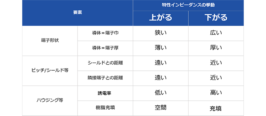
I think you can see that the element of "going up" requires a large amount of space and a small conductor. Since resistance loss power is R×I2, there is a trade-off relationship in which increasing R increases I.
Then, if you ask whether the resistance loss can be optimized by the characteristic impedance, there is actually a "just right place = the place where it becomes the minimum". There are coaxial cables, but there are two main types, 50Ω and 75Ω. In fact, it is the impedance of the optimum solution under each condition. The characteristic impedance also depends on the dielectric constant of the insulator, so if polyethylene is used as the insulator and rounded at a good cut, it will be 50 Ω, and if the insulation layer is air, it will be 75 Ω. and its characteristic impedance surpasses that of coaxial cable and is very popular today (double that of differential). In any case, the characteristic impedance must be matched with the relevant connections before and after. And in current high-frequency applications, the selection of characteristic impedance, which has become the de facto standard, is well-balanced in terms of reducing and optimizing resistance loss, so I don't think it's necessary to show much originality in this area. increase.
Now, let's put aside the topic related to resistive loss for the time being and move on to dielectric loss.
Dielectric loss
Dielectric loss: Is it okay to use materials that easily heat up in microwave ovens?
In addition to resistive loss, there is also loss in which energy is converted into heat in an insulator, and this phenomenon is called dielectric loss. I will briefly explain what is happening. In the high-frequency electric field, the material molecules are shaken and generate heat. By the way, when heated in a microwave oven, there are things that warm up easily and things that don't. When using a plastic bag or tray for microwave heating, I think that some people may have experienced that the bag or tray itself may or may not get warm. And in the insulators of the transmission lines carrying high-frequency electrical signals, something similar, albeit much milder, is happening in a microwave oven. For this reason, if a material that easily heats up in a microwave oven is used as the insulator for the transmission line, the loss of signal energy will increase. I would like to talk about that in detail.
Attenuation constant, dielectric loss, and dielectric loss tangent are determined by material and frequency
In this column, I try not to use complicated calculation formulas as much as possible, but this time I'll start with something a little more complicated. If you are going to have a headache, please skip this item. There is a method called "distributed parameter circuit" as a method to unravel the analysis of transmission lines. Roughly explained in a practical interpretation, it is an attempt to analyze electromagnetic phenomena using an electric circuit approach.
α=R/2x√(C/L)+G/2x√(L/C)
Of these, the second term, "G/2x√(L/C)," corresponds to the dielectric loss. RLCG is called R = resistance component, L = inductance component, C = capacitance component, and G = conductance component of the transmission line. Here, the bender is the conductance component of G, and at high frequencies the relationship G = tan δ × ωC holds. The tan δ used here is a parameter called the dielectric loss tangent, and it is a parameter that indicates the ease with which a material can be warmed in a microwave oven. Based on this, if you transform it further
tanδ×ω×C×√(L/C)/2=1/2×tanδ×ω√(LC)
Also, since √(LC)is quite infinitely equal to √ε trueçthe (true) permittivity of the material,
1/2×tanδ×ω×√εtrue
becomes. The (true) permittivity is used because the "relative permittivity", which is the ratio of the permittivity of a material to the permittivity of air, is often used in practice, and it is established that it is simply referred to as the permittivity. Therefore, the above, which is the academic (?) original dielectric constant, was regarded as (true) (Is it like the relationship between the red panda and the giant panda?). ω is angular frequency = 2πf = doubled frequency multiplied by pi. In other words, the dielectric loss depends only on the dielectric loss tangent, the dielectric constant, and the frequency, which are the eigenvalues of each material. There are no structural requirements such as size.
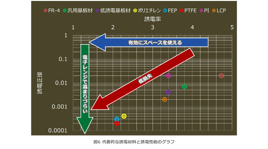
Spread of high-speed transmission and low-dielectric materials
As mentioned in the previous section, dielectric loss is proportional to frequency. On the other hand, resistive loss is proportional to √f = frequency raised to the power of 1/2, as mentioned in the section on "skin thickness". At low frequencies, resistive loss is dominant, but as the frequency increases, dielectric loss becomes more pronounced. At present, we are catching up and overtaking, and dielectric loss is becoming a more serious issue. As mentioned in the previous section, the lower the dielectric loss tangent (proportional) and dielectric constant (proportional to the power of 1/2), the smaller the dielectric loss. As a direct effect, the dielectric loss tangent is larger, but if the dielectric constant is lowered, the inner metal can be used more (characteristic impedance), which contributes to the reduction of resistance loss, so both are equally important. parameters. Against this background, various low-dielectric substrate materials have been developed for PCBs to replace the conventional FR-4. I hear that companies are competing with each other in terms of low dielectric strength while maintaining structural and process resistance characteristics. For FPC, the LCP type with much lower dielectric loss tangent/lower dielectric constant than the conventional material PI (polyimide) and the ultra-low-loss PTFE type have been developed.
FFC for high-speed transmission and its connector
We have also released a solution product that applies the low-loss technology we have explained so far. It is a high-speed jumper solution of over 25 Gbps that combines low-loss FFC with our Auto I-Lock structure series FFC/FPC connector, which boasts high compatible data rates due to its low reflection. As introduced in "Conductor Shape and Material," a more detailed explanation is provided in "25 Gbps Compatible Floating structure Board to Board Connector" under "High-speed Transmission Solution." We would be delighted if you could take a look at this product page as well.
At the end
With each passing year, the development of components and materials related to high-speed transmission is becoming more and more dizzying. As mentioned at the beginning, the connectors we develop are also gradually moving from a performance improvement that focused solely on characteristic impedance to a stage where we are focusing on reducing resistance loss and dielectric loss. As speeds continue to increase, the impact of the "smoothness" of metal surfaces due to the skin effect may become more pronounced, and I believe that the development of low-dielectric materials will continue to progress. Even in such an era, IRISO hopes to continue developing products that "reliably connect" and delivering them to our customers!
Here you can find our various initiatives for high-High-speed transmission Connector. Please take a look.