
- Top
- Technical Info
- column
- How many amperes can flow when the current is divided into multiple pins?
Connector rated current and shunt current
Connectors have a stipulation called rated current. In the case of our company, the rated current is "the current value that raises 30°C when all poles are energized." The temperature rise during energization is included in the product's rated temperature (permissible temperature), so if the temperature is 30°C lower than the rated temperature, the full current can flow to all poles. This is generally the same for our competitors. There are cases where a different rated current is provided for specific environments such as low ambient temperatures, but there is also consistency with UL standards, etc., and most products define a rated current value that causes a 30°C rise. I'm here.
However, when this becomes a branch stream, it seems that each manufacturer responds differently. For example, how would you respond to the request, "This connector's rating is 1.0A, but I want to use 3 pins to flow 3.0A." In such cases, we will consult with the customer and in many cases will recommend a shunt. On the other hand, there are some manufacturers who consider the effect of shunt flow variation and say that it is not recommended. Why is there such a difference? This also depends on the connector type.
In this article, I would like to discuss a little about shunting, while also touching on the heat generated in the connector due to energization and dealing with large currents.
Why do connectors get hot?
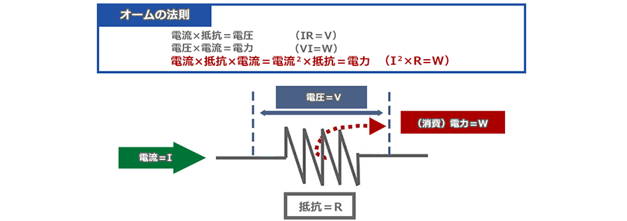
ohm's law
When a current = I flows through an electrical resistance = R, a voltage is generated before and after it. And "power = W" is consumed in electrical resistance. The relationship between them is Ohm's Law, as shown in the diagram below.
The content of this column is "Resistive Loss" and "Dielectric Loss" Signals Change to Heat and Become Smaller?, so please refer to it.
Then, where does this consumed W go? It turns into heat. This phenomenon is the reason why devices and parts that conduct electricity, such as power cables, generate heat. In other words, the "resistance = R" into which the current is flowed becomes the heat source. All metals have electrical resistance, and the terminals of connectors that conduct electricity are no exception to this, and become a heat source when energized.
In order to reduce this heat as much as possible, it is necessary to reduce W when the same current flows, so it is thought that the smaller the R, the better. Let's think a little about R = electrical resistance.
The electrical resistance of a cylindrical conductor is determined by the metal type, length, and cross-sectional area.
To think about R = electrical resistance, let's start with a simple model.
Each metal has a value called volume exchange resistance, which indicates how difficult it is for electricity or current to flow. Conductivity, which indicates how easily current flows, is proportional to this reciprocal. And in the case of a cylindrical conductor, it has the electrical resistance value shown in the figure.

Electrical resistance = R = ρ x L/S
Here, I will explain a little image story by comparing it to a road. When driving a car, the smoother the road, the less tired you are. The resistance characteristic resistance value = ρ indicates the unevenness of the road surface. Also, the wider the road, the more stress-free you can drive. As for the current, the wider the cross-sectional area of the conductor, which corresponds to the width of the road, the less the consumption. If you drive a long distance, you will still get tired, so the longer the distance = L, the more electricity will be consumed. In addition to roads, I think it would be nice to imagine water hoses and straws. "Resistance" when an object passes is common to all.
Now, according to this formula, "a material with a low resistance value, a wide cross-sectional area, and a short conductor" has a low electrical resistance value. The energy used for heat generation, which is indicated by I2×R, should also be reduced. If that is the case, the temperature rise can be considered as it is, but the situation becomes slightly more complicated, so let's consider it next.
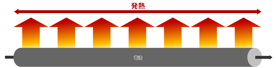
Heat generation in a cylindrical conductor
This figure is an image diagram of a cylindrical conductor generating heat while current passes through it. As the electric current flows through the cylindrical conductor, which has electrical resistance, it continues to generate heat in the length direction.
If the conductor is shortened here, the resistance value will decrease, so let's shorten it a little. Can temperature rise be suppressed?
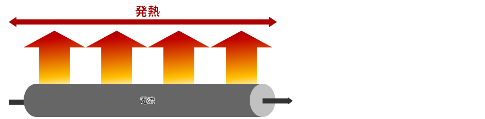
This will lower the resistance. It's just a sensory story, but from this image, I get the impression that the heat doesn't change much. By shortening the conductor, the resistance value and the total amount of heat generated are also reduced. is.
Let's talk about images for a moment.
What would happen if we brought a heater that could keep the 6 tatami room warm and comfortable in the middle of winter to another space? If you use it in a 12 tatami room, it will probably be a little cold. If you bring it into a large space such as a gymnasium, it will not work. It really doesn't get warm at all except near the heater.
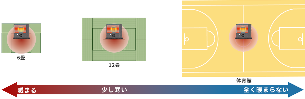
In this way, even if the amount of heat generated is the same, the effect will decrease if the object to raise the temperature increases. Conversely, as in the case of the cylindrical conductor, even if the resistance value is lowered by shortening the length, the temperature rise in the limited area does not change.
In other words, it seems that the temperature rise is determined only by the low efficiency of the material and the cross-sectional area of the conductor, but are there any exceptions? Let's think for a moment while giving an example of a non-dependent example.
Cases where length does not affect Allowable electric current amount of electric wire and heating wire
So far, we have explained using a cylindrical conductor as a model.
There is a definition of allowable current for electric wires, and in particular, the allowable current for "placed one wire in a space with a margin" is a simple phenomenon, so the calculation formula is solid. The formula itself contains logarithms and is somewhat complicated (it is posted on each wire manufacturer's site, so please search for it if you are interested), but the basic idea is roughly as follows. (In the actual formula, it is transformed into a form that can calculate the direct allowable current amount).
・It is calculated from the phenomenon around the unit length, and when it is long, the same phenomenon continues all the time, so it is uniquely determined without depending on the length.
・Calculate the amount of heat generated when current flows through the conductor
・Calculate the flow of heat to the surface of the wire = heat transfer
・Calculate the heat radiation from the wire surface.
・As a result, the heat trapped inside is calculated, and the temperature rise of the conductor, which is the part where the temperature rises the most, is calculated.
・The allowable temperature is the current value that makes the difference between the ambient temperature and the rated temperature (maximum allowable temperature) of the wire equal to the temperature rise calculated above.
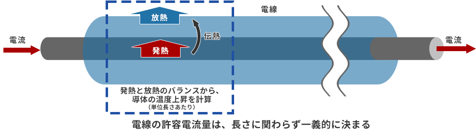
Although it overlaps with the explanation in the previous section, when the wire is long, the total amount of heat generated increases, but the temperature rises over a wider section, so it does not depend on the length. In other words, for wires that are laid loosely and loosely, resistance increases with length, but it does not depend on temperature rise.
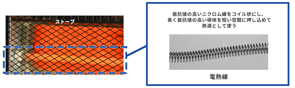
But what if you don't have the luxury of time? For example, if wires are clumped together, a large heat source exists in a narrow space, so the length of the wire seems to depend on the temperature rise (of course, there is also the factor that it is difficult for heat to escape). The most prominent of these is the electric heating wire.
The heating wire is made of nichrome wire, which has a high resistance value, and is made into a coil shape. In a configuration where a long object can be squeezed into a narrow space like this, the length of the conductor also has an effect on the temperature rise.
In summary, what seems to contribute to the temperature rise is the electrical resistance value within a certain section = the metal material, the cross-sectional area, and depending on the condition, the length of the conductor. But what about connectors?
Connector terminal shape and heat generation/temperature rise
Terminals, which are conductors in connectors, do not have a simple structure like cylindrical conductors. Depending on the function and mechanism, the metal is stretched, squeezed, and pulled into a complex shape, and there is also contact with the Mating partner, so it is not easy. Nevertheless, the basic idea can follow the contents that have been followed up to the previous section.
Connector terminals have several areas that tend to become heat sources, and I would like to look at two examples.
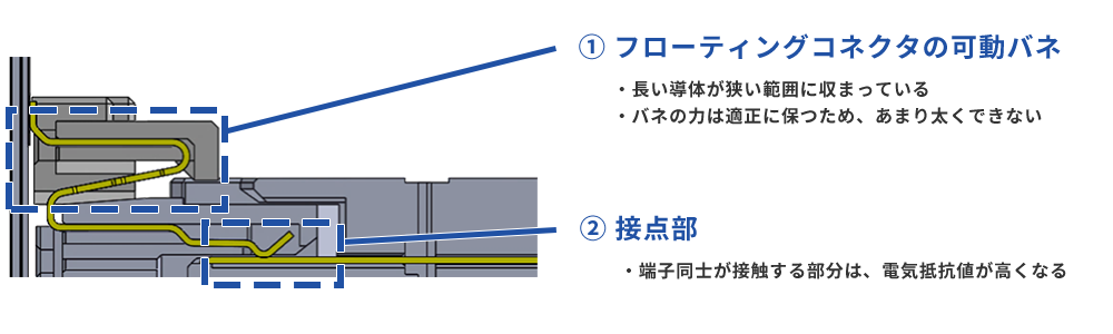
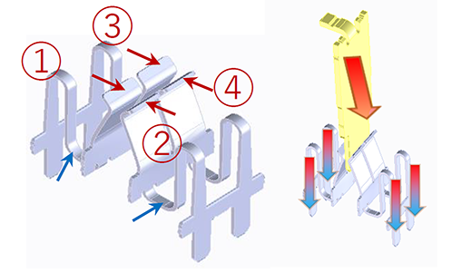
Shown above is a cross-section of the Floating Connector showing the state of the terminals.
The first one, which tends to be a heat source, is the Floating structure Floating spring part. As shown in the heating wire example earlier, a long conductor fits into a narrow range. Also, since the force of the spring must be maintained at an appropriate level, it cannot be made too thick, that is, it cannot have a large cross-sectional area, which inevitably tends to result in a high resistance value.
The second is the contact point. The parts where the terminals are in contact with each other are more difficult for current to flow than the metal part, and in other words, the electrical resistance is higher, so these parts tend to become heat sources. In the previous explanation, I compared the conductors to roads and water hoses, but it's similar to the flow stagnation at highway junctions and hose joints.
To put it the other way around, the structure of these two places will be the key to devising a high-current connector. For example, shown below is a terminal diagram of our 10122 series of miniature high current (15A) Floating Connector. This product has a unique 4-point contact structure, and by partially dividing the Floating spring, it is possible to achieve both heat suppression and mechanical properties.
We are also currently developing a 30A type that uses a new Floating spring mechanism. Now, I have detoured a little, but I would like to proceed to the story of the branch stream that I talked about at the beginning.
How is current shunted? Resistance variation
Let's consider the case mentioned in the introduction section, "This connector's rated current is 1.0A, but I want to use 3 pins to flow 3.0A" as an example.
If the electric resistance value is exactly the same in the shunt section including the connector, the current of 3.0A will be equally shunted to each pin by 1.0A. Now, let's look at the case where one of the three lines has a higher resistance by ΔR to see what happens if there is variation in the resistance of the connector.
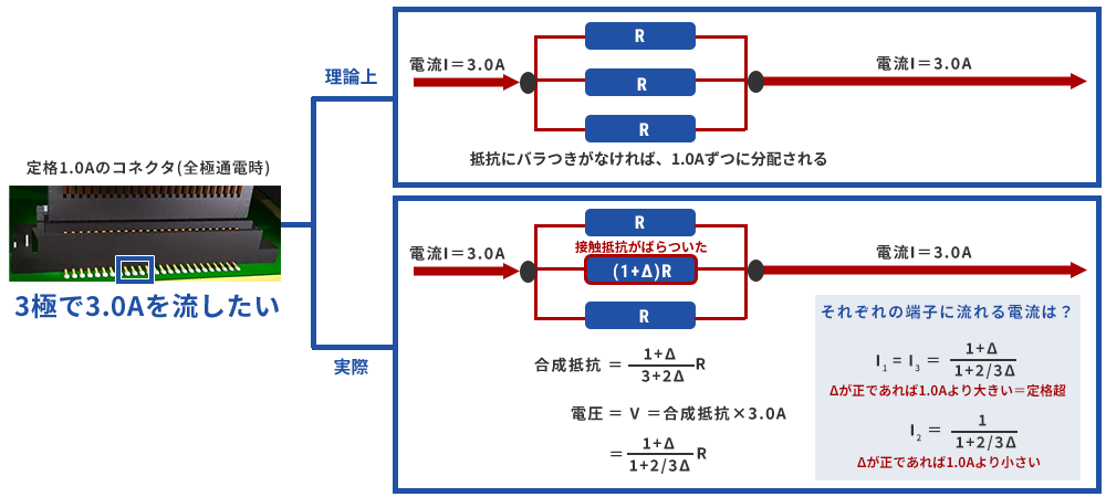
Although we omit the calculation in the middle, it can be calculated with a simple circuit calculation as shown in the figure. Let's look at the current that finally flows through each terminal. The currents I1 and I3 for paths with no resistance variation = R are both (1+Δ)/(1+2/3Δ) amps. If Δ is a positive value, Δ>2/3Δ and the numerator is larger than the denominator, so I1=I3>1.0A, exceeding the rated current value. On the other hand, the current I2 of the line with the resistance variation is 1/(1+2/3Δ) A, and since the denominator is larger than the numerator, it is smaller than the rated 1.0A. As you can see from the calculation, the sum of the three currents is, of course, 3.0A.
Current tends to be biased toward the direction of flow. This is the same for water flow and air flow, even if it is not an electric current. Therefore, the current is distributed from I2, which has high resistance, to I1 and I3, which have low resistance due to the slight difficulty of flow.
By the way, I1 and I3 have exceeded their rated current values. Does this mean that it is unusable? Going back to the beginning, the definition of rated current is "the current value that raises 30°C when all poles are energized". Now, let's look at the resistance loss, which is a heat source related to temperature rise, in comparison with all-pole rated current conduction.
Change in loss due to shunting (1) Total loss is less if flow is allowed
Consider the following model to compare resistance losses related to heat generation. When 1.0A current is supplied to each of the 3 pins independently according to the definition of rated current.
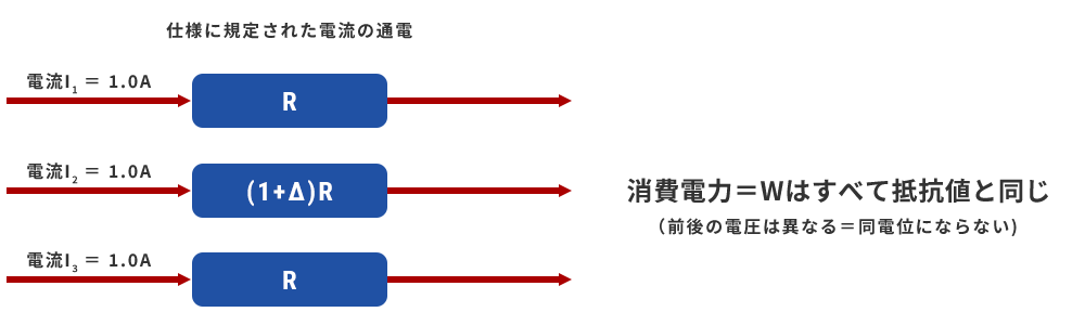
Since the potential difference V=IR before and after the resistor is different, it is a model that is a bit unthinkable as a specification that splits and sends one power. The power consumed by each resistor is W=I2×resistance value, and since the current I is 1.0A, it is equal to the resistance value. Combining the three gives (3+Δ)R.
On the other hand, the integrated power consumption for the three resistors in the shunt model seen in the previous paragraph is the voltage value multiplied by the total current of 3.0A, so (1+Δ)/(1+2 /3Δ)×3.
Let's graph each total power in comparison with the power when Δ is a negative value, that is, when ``the three resistances do not vary and all are R'', including the case where the resistance value drops by one. I was.
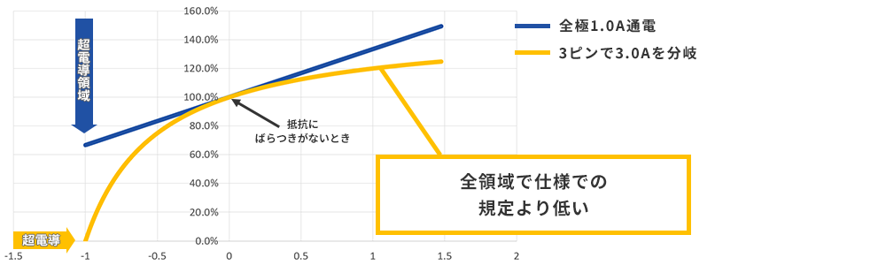
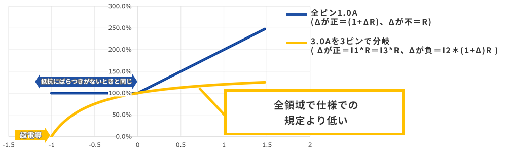
Comparison with total power consumption when there is no variation in resistance
The orange line is the total power consumption in the resistance part of the shunt model when the resistance value varies, and the blue line is the case when an independent 1.0A is applied to the connector in all poles. For both lines, when Δ is positive, the combined resistance value increases, so the power consumption becomes higher than when there is no variation, exceeding 100%. However, what should be noted here is that the orange line is lower than the 1.0A all-pole conduction as specified. Why does this difference occur with the same total current of 3.0A?
As mentioned above, current has the property of being biased toward the direction where it is easier to flow. Rather than dividing the current into three equal parts and forcing the same amount of current to flow even where it is difficult to flow, it is better to divide the current as you want it to flow, resulting in a more efficient flow. Therefore, the total power consumption is lower.
From these results, it can be seen that, strictly speaking, there are pins that exceed the rated current value at the time of shunting in connectors with variations in the resistance value, but the temperature rise that is the basis for the rated current specification is stipulated. I think you will feel that it is likely to be lower than when you use it to the fullest. But what about more localized fevers? Let's take a look at the individual pins that consume the most power in the two models.
Change in loss due to shunting (2) What is the heat generation of individual pins?
In the shunt model, the voltage value before and after the resistor is the same, so the "pin with the highest current flow" has the same current value. Each has a different pin depending on whether Δ is positive or negative. For details, see the following chart legend.
Comparison with power per pin when there is no variation in resistance
In this way, even when looking at the power consumption of individual pins, the result is that the orange line falls below the blue line across the entire range. Even if you look at the power consumption of individual pins that cause localized heat generation, it means that the power consumption at the time of shunt is lower than the conditions specified in the specifications. It's a different story if it's due to a defect such as a mounting defect or foreign matter getting caught (even if it's not energized alone in the first place). Diversion seems to be fine.
But are there any cases where it matters? Next, let's consider a case where the shunt current distribution changes due to factors other than the connector.
As an aside, we have a technology called 2-Point Contact to prevent foreign objects from getting caught, so we hope you will take a look at that as well.
Influence of wiring all the way to the connector
Wiring materials are usually included between the power supply, connector, and supply target. For example, electrical wires and circuit board traces. These are intervening when shunting the current, but if this is the connection distance, the routine in the board layout, or the wiring after branching has a value much larger than the resistance value of the connector, the current distribution is independent of connector resistance.
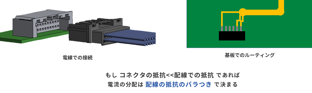
In other words, if the resistance of this wiring is large and varies, a biased current will be distributed to each pin regardless of the state of the connector.
Let's take a slightly extreme example, but consider the following model with variations in wiring resistance.

The power consumed by each resistor here is I12, I22, and I32 times more than when exactly 1.0A flows. The power consumed by three resistors is (3+4Δ+2Δ2)/{3×(1+2/3Δ)2} times. Again, let's see a graph of the total power consumption of the connector and the power consumption of the pin with the highest consumption (note that the graph notation is slightly different than before).
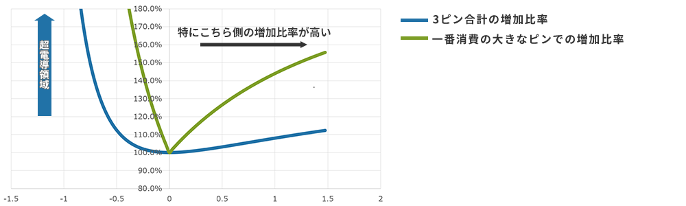
Power consumption at the connector part, increase ratio from the case where the current is uniform
Since the approximation is also done at the premise stage, when Δ is negative and large, it includes situations that are unlikely to occur in reality, but even if the total value of 3 pins or a single pin is seen, it is higher than the state where the wiring is uniform across the entire area. It is Especially when looking at a single pin, a large increase in power is confirmed where a large amount of current is distributed. In other words, when splitting a high current below the rated current and sending it through a connector, there is the possibility of unintended heat generation depending on the state of the wiring up to the connector and beyond.
I think that this kind of case is probably assumed by other companies in the same industry in cases where "split is not recommended". Also, when looking at the type of connector, this phenomenon may become more pronounced in connections via wires, such as wire-to-board connectors and wire-to-wire connectors. In the case of our company, I explained at the beginning that "in many cases, after consulting with the customer, we recommend splitting the flow", but during this consultation, we confirm that there is no such risk.
As a conclusion, if the resistance value of the wiring part is stably divided equally, it is possible to pass the current up to the rating x the number of distribution pins, but when there is concern about the balance of the wiring part It is necessary to have a suitable allocation. Another point that is slightly different from what we have discussed so far is that if the current is branched, for example, if one connection is completely broken, the flow will completely stop because the current is branched. There is also a risk that the perception of "occurrence of trouble" will be delayed without stopping. We can make various proposals and discussions based on these points, so if you are considering using our connector, please consult with our sales staff or contact us via our website.
At the end
With the trend toward smaller electronic devices, I feel that there are more and more cases where people say, "I want to use the same connector for low-power signals and power because of the board layout, but I can't use a large one." . In such cases, there are many cases where it is difficult to make full use of connectors with a small rated current value. , as soon as I picked up this subject.
We also offer the 10143 series Board to Board Connectors which combines a 0.5mm pitch connector with a 0.5A rated signal line and four 3.0A power lines. Please check it out. We also recommend the 10122 series high-current Floating Connector introduced in the text.