
- Top
- Technical Info
- column
- Mechanical and Electrical Resonance
What does the word "resonance" mean?
Have you ever had a conversation where the word "resonance" was either electrical or mechanical, and the conversation didn't flow smoothly? In our case, we have released a connector called Z-Move structure that has excellent mechanical vibration resistance, so 80 to 90 percent of people think of mechanical resonance when they hear the word resonance. When talking about electrical resonance, you need to be very clear about it or some people will get confused. Depending on the work or field of expertise you are involved in at the time, you may think of different things from the same word. Or there is the word resonance, but how is it different from resonance? How should you use it differently? Resonance is a word that you often hear, but it is surprisingly complicated.
For example, the word "destruction" is not only used to physically destroy something, but also to describe phenomena or states such as "price destruction," "destroying the system," and "destroying common sense," but no one would find this confusing. Incidentally, destruction is "the loss of the shape, function, or properties of something as a result of the application of some kind of force or influence, or the act that causes this."
If we can break down "resonance" to the level of words like "destruction," then I'm sure we will be able to understand it immediately without confusion even if the word is presented in a different situation. In this article, I would like to clarify the meaning of resonance and touch on individual technical aspects.
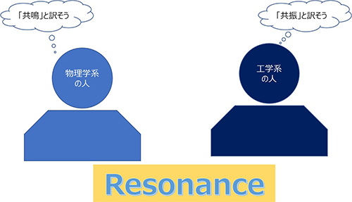
Translating Resonance: Resonance or sympathy?
In fact, both resonance and sympathetic vibration are translations of the same English word, "Resonance." In other words, there is no distinction between the two, at least in English. In the world of physics, "sympathetic vibration" was the preferred translation for this word. It was first used to describe sound-related phenomena, but it seems to have become common to use this translation for other vibrations as well.
On the other hand, in the field of engineering, it seems that the translation "resonance" is often used, which may be because it felt strange to say "resonance" = "sounding together" in the resonance phenomenon of electric circuits. (Although resonance is sometimes used) In essence, both refer to the same phenomenon = Resonance, and there is no essential difference, but rather the preferred name is different due to a slight difference in the society to which it belongs. Is it like throwing garbage in the Kanto region, throwing it in the Kansai region, and throwing it in the Hokkaido region? Either way is correct, so let's not get confused even if the words we use are different, but respect each other and get along well.
What does it mean to vibrate and sound together?
Let's start with resonance, a familiar phenomenon. If you have two guitars and you pluck a string on one guitar, the same string on the other guitar that's not being touched will ring. Also, in a rarer case, which only happens if you're listening to music at a very loud volume, the guitar may ring out of nowhere, attracted by the music. This is resonance, or sympathetic vibration.
Familiar Resonance Phenomena
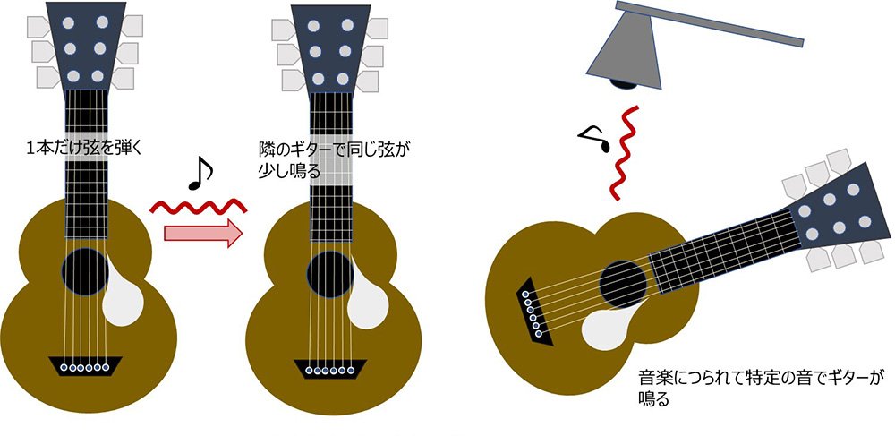
Image of resonance
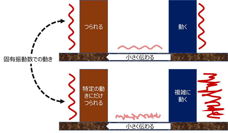
In other words, resonance is a phenomenon in which, when there is something moving nearby, it is influenced by it and makes the same movement, even though the influence is only slight. It is not that it is influenced in all cases, but rather that it only moves when there is a specific, specific frequency, which will be described later, and the originally small influence becomes larger and larger if it continues. This is the same for electrical circuits and physical things, but in the example of the guitar mentioned above, it corresponds to the frequency of the pitch produced by the strings. Also, if the other object nearby has a random frequency movement, it will trace and move in a form that extracts only the vibration of the frequency that it is easily influenced by. It's like a guitar string that responds to a specific sound in music. The image is something like the following diagram.
Now, I would like to explain the difference between mechanical and electrical frequencies, or natural frequencies, at which these phenomena occur and are sensitive.
Natural frequency Mechanical vibration is determined by mass, rigidity, center of gravity of vibration, etc.
Rigidity and mass = the effect felt on pitch
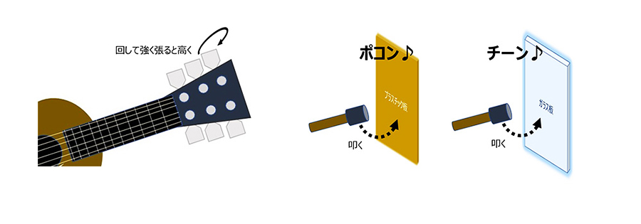
Every object, or perhaps even every part, has a specific frequency at which it tends to vibrate. Roughly speaking, this is determined by the mass and rigidity of the vibration area.
The higher the rigidity, the higher the frequency. A tightly taut string will produce a higher pitch than a loosely taut string, and when you strike something hard (like glass) it will produce a much higher-pitched "t'ing" sound than plastic. Even when comparing two plastics, I think many people have the impression that the harder one produces a higher-pitched sound based on their physical experience.
The smaller the mass, the higher the frequency.
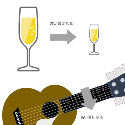
If two instruments are made of the same material but have different masses (sizes), a smaller glass will produce a higher pitch than a larger one, and the same can be said for the difference in pitch between the length of the plates of a xylophone or a steel bar. A thinner string will produce a higher pitch than a thicker string.
(In everyday life, there are many examples of objects with the same size and shape but different masses; objects with a higher mass also tend to have higher rigidity, so the natural frequency = pitch is a difficult trade-off...)
Perhaps the closest analogy would be the difference in sound you get when you hit a plate of glass and a plate of metal.
Speaking of sound, in fiction we often see descriptions of a singing voice breaking glass, such as a wine glass.
That is also a case of hitting a wine glass with a sound that matches its natural vibration frequency, so it is a case of resonance. In reality, it is quite difficult to break a wine glass with the level of a human voice, but there are many science experiments in which wine glasses are broken by sounds emitted from a speaker.
There are many experimental report and video clips on the web, so if you are interested, please do a search.
Natural Frequencies Get Complex Quickly
Doesn't the pitch of a glass change when it is hung from a table or when it is held in your hand? This is because the mass and rigidity of the vibration range change due to the influence of the surroundings. In a simpler example, when you press down on a guitar string, the pitch changes and becomes higher. This is because the fulcrum of vibration has changed, and the mass between the fulcrums has become smaller. It seems that various factors are involved in determining the natural frequency.
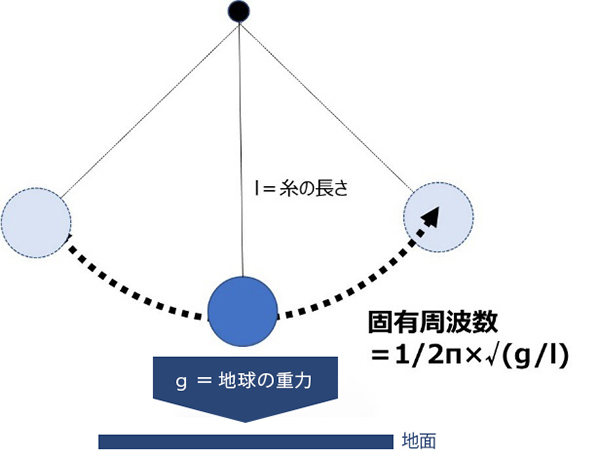
For springs, pendulums, or musical instrument strings, which are taught in high school physics, the natural frequency can be calculated with a relatively simple calculation. In particular, the frequency of a pendulum is determined by the gravity of the Earth (=g) and the length of the string alone, regardless of mass or the rigidity of the object, if the string is massless and the weight has no size (or the center of gravity is at the end of the string), and is 1/2π×√(g/l). The longer the pendulum string, the lower the frequency, and the shorter the frequency, the higher the frequency. It's the same as a guitar string.
When you think of a pendulum, what immediately comes to mind is a swing? However, with a swing, it's not that simple. The string that makes up the pendulum is a chain, so mass cannot be ignored, the center of gravity changes depending on how tall you are, the fulcrum also changes when you hold the chain in your hands, and it becomes a fairly complicated phenomenon when the rider moves up and down. It's no longer possible to put it into a simple equation. Incidentally, if all other conditions are the same and it's just about being tall, qualitatively the natural frequency is higher for taller people, and it is also higher when standing and rowing than when sitting. Compare this with the equation for the pendulum.
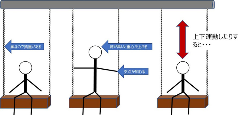
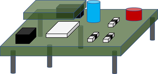
The addition of a small element to the swing rather than a pendulum has made it more difficult to calculate the natural frequency. Things in the world have complex shapes, many parts that serve as fulcrums for vibration, and various things are combined, and the center of gravity of the vibrating parts varies, so quite complex calculations are required. For example, in a board on which components are mounted, the screwed parts become the fulcrums for vibration, and the mass of each component mounted between the fulcrums affects the center of gravity of vibration, so it is not easy to grasp the state of vibration. Each part can have multiple natural frequencies, and the phases can also differ.
On the other hand, as explained in "What does it mean to vibrate and sound together?", "even if the originally small influence continues, the phenomenon of it growing larger and larger" is called resonance, and it occurs at the natural frequency. There are various external factors in the environment in which an object is used and placed, and in order to determine whether it can really be used safely and securely in that environment, it is necessary to understand the natural frequency and the possibility of resonance occurring in the usage environment.
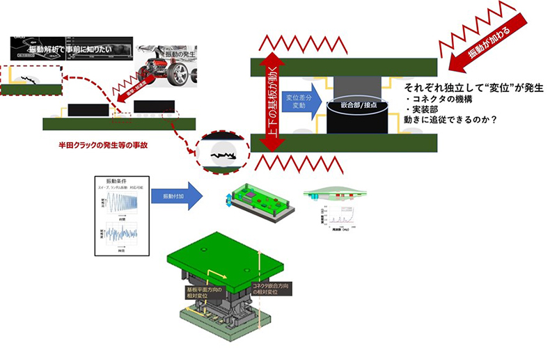
Vibration analysis using CAE and the "Vibration Analysis Service" provided by IRISO
To analyze such complex vibration phenomena, CAE using the finite element method and other methods is used to perform vibration analysis to analyze when an actual product will cause a resonance phenomenon and whether it can withstand that resonance. Although it is difficult to verify each one by hand calculation, various problems can be predicted in advance by analyzing the product based on the mass and rigidity of each component that makes up the board on which the parts are mounted. This is also important when selecting connectors.
IRISO offers vibration analysis services to customers considering the specifications of our products, proposing optimal products and even suggesting changes to the board layout depending on the analysis results. The link below provides an introduction to this service. It also briefly explains the problems that vibration can cause for connectors, so please take a look.
Now let's move on to the topic of electrical resonance.
Is electrical resonance complicated?
"You can't see electricity so you have no idea!"
I've heard people who are not electrical engineers say this. Mechanical resonance is based on vibration, which is easy to understand because you can see it, hear it, feel the difference in pitch, touch it, or feel it when you're there, but it may be hard to imagine it when you hear the word "electrical resonance". I studied electrical engineering when I was a student, but I still get lost sometimes (I'll ignore the possibility that I didn't study seriously). One effective method for managing production sites is "visualization". For example, it is about making things that are not clear at a glance, such as the progress of production or the occurrence of defects, visible to everyone and sharing them. It's something I keep in mind in other columns about electricity, but I would like to explain it in a way that is as easy to understand as possible.
AC, Frequency and Phase
As you probably learned in junior high school science, there are two types of electricity: direct current and alternating current. (The electricity used for signals is a composite, with DC and AC components, but we'll leave that aside for now.)
One of the advantages of AC is that it is easy to transform voltage (a famous related example is Nikola Tesla, the disciple who defeated Thomas Edison, so if you're interested, please look him up), but please keep in mind that understanding AC behavior is also important for signal transmission, as this will be covered in future articles.
Now, the electricity sent to homes in the Kanto region of Japan is generally "AC, 50Hz, 100V voltage."
In Kansai, the frequency is 60Hz, but since it's a nice round number, let's use 50Hz for easier explanation.
50Hz is a unit of 50 cycles per second, and as an example, we have illustrated the movement of 50Hz electricity over 0.15 seconds.
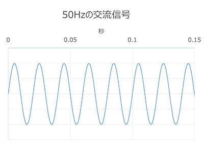
When it moves this much in 0.15 seconds, it actually vibrates, even though it is invisible to the naked eye.
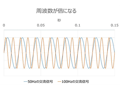
And there is electricity of different frequencies.
When the frequency is doubled by 100Hz, it vibrates busier. In terms of sound, it feels higher. By the way, since it's doubled, it's the difference between an octave. To digress a little, why is an octave = 8 even though it's doubled? Because the 8th note of Do-Re-Mi-Fa-So-La-Si-Do is the same as the 1st note, Do. However, the reason why the scale has 7 notes in the first place is that it was created naturally in an attempt to achieve a pleasant sound and harmony of the scale. There are parts of octaves and good sounds that suggest resonance.
In the illustration it is limited to twice the frequency, but the frequency of these vibrations can of course be 10 times, 100 times, 1000 times... mega is a million times, giga is a billion times, and so on, and can be infinitely faster, in the range known as high frequency.
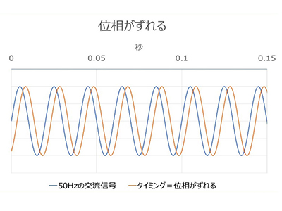
On the other hand, there is the concept of phase.
Even if the vibrations have the same period or frequency, the timing of when they start and end will vary, and the difference when compared is called a phase shift.
The image of these three diagrams will be important when we move on to the topic of resonance, so I hope you can understand them at least roughly.
Vibrations and alternating currents interfere with each other in the form of waves.
First, what is interference? Interference is "the phenomenon in which two or more waves of the same kind meet at the same point, overlapping and strengthening or weakening each other." Just as the number of times they vibrate is called "frequency," both alternating current electricity, as explained in the previous section, and the vibrations that shake things are waves. Therefore, when two or more things overlap, they strengthen or cancel each other out.
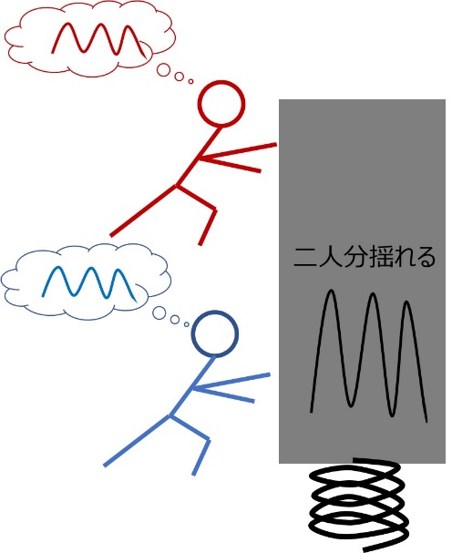
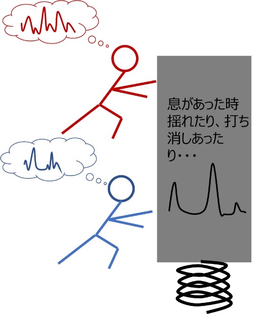
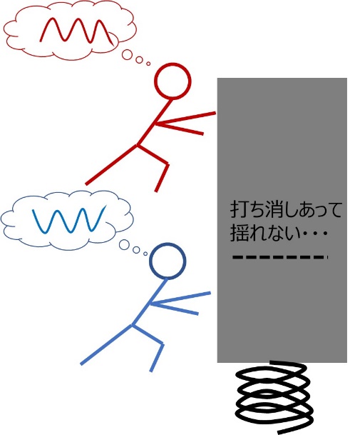
Imagine two people with equal strength working together to swing a large, heavy object up and down on a strong spring.
If two people are perfectly synchronized, their forces will combine and cause a large swing. If two people are just shaking randomly, they will only move large when they happen to be in sync, and will only move small amounts the rest of the time, or their forces in opposite directions will cancel each other out and they won't move at all. If two people try to make completely opposite movements, they will completely cancel each other out and there will be no sound. Something similar happens with electricity. This is the image I want you to keep in mind as a premise.
Let us now turn to an explanation of two phenomena called resonance in electricity.
Electrical Resonance
① Vanishing and infinity of impedance
If someone asks "What is impedance?" we answer "Voltage ÷ Current." When we talk about impedance at our company, the question is often "What is (characteristic) impedance?", which is what happens when you try to communicate things as accurately as possible. In situations where there is no room for misunderstanding, such as impedance matching and impedance profile, the word "characteristic" is omitted, so in some industries many people assume that impedance = characteristic impedance, but it is actually a specific type of impedance. As stated in the glossary linked to above, characteristic impedance is also actually "voltage ÷ current."
If you thought, "Huh? Isn't 'voltage ÷ current' the (electrical) resistance in Ohm's law?", you're mostly right. Resistance is also a type of impedance. There is electrical resistance in both direct and alternating current, but when it comes to alternating current, where electricity is moving, elements/components called capacitance (electrostatic capacity) and inductance appear (although capacitance is treated as a storage element even in direct current). This is where the concept of phase shift between voltage and current comes into play. It's a bit complicated to say that impedance becomes a complex number with not only magnitude but also angle, but I think it's enough for now to just think that it can no longer be added up by simple addition. First, let's take a quick look at what resistance, capacitance, and inductance are.
First, there is resistance, which is familiar from Ohm's law.
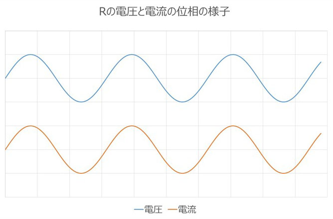
Electrical energy is lost in the form of heat. The voltage and current have the same phase, and impedance is a real number in complex terms. It is measured in Ω, the same unit as impedance. Resistance in connectors and transmission lines is explained in more detail in the column "Resistance Loss and Dielectric Loss: Do Signals Convert to Heat and Become Smaller?", so if you're interested, please refer to that as well.
Resistance: R
・Converts electricity into heat and consumes it (loss element)
- Frequency independent
(In the real world, this increases due to the skin effect, etc.)
- The voltage and current within the element are in phase
Next is capacitance.
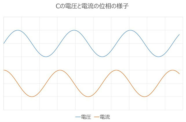
What is called a capacitor is a component that has this capacitance function. It is an element that stores electrical energy according to the voltage, or the voltage is determined by the amount of stored electricity, and once a balance is achieved due to its nature, it does not pass direct current, but has the property of passing currents with steeper voltage changes and higher frequencies more easily, so it is often used to take advantage of this. The current leads the voltage in phase by π/2. In complex terms, impedance is a negative imaginary number. The unit of impedance is Ω, but the unit of F (farad) is used as a constant for the element preceding it.
Capacitance: C
- Stores a charge proportional to the voltage (lossless element)
When the voltage changes, the excess or missing charge
Take in and give out electric current
The higher the frequency, the greater the voltage change.
Easy flow = lower impedance
・The phase of the voltage and current is shifted as shown in the figure.
Finally, the third factor is inductance.
Components and coils known as inductors have this function. Because they dislike changes in current, they behave in a way that opposes changes in voltage, so the higher the frequency, at which the voltage is forcibly changed, the more difficult it becomes for current to flow. The current lags behind the voltage in phase by π/2. In complex terms, impedance is a positive imaginary number. The unit of impedance is Ω, but the constant of the element preceding it has the unit H (henry).
Inductance: L
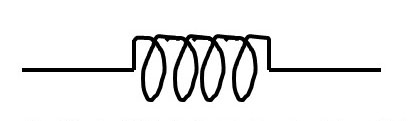
- Voltage that opposes the change in current (lossless element)
・The more movement there is in the voltage source, the more the current can be reduced
The more intense the movement, the higher the current.
Less flow = Increased impedance
・The phase of the voltage and current is shifted as shown in the figure.
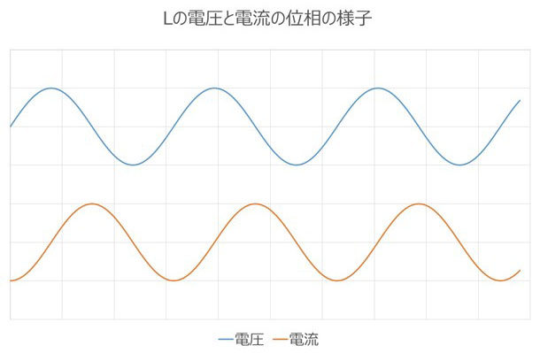
What we want you to pay attention to here is that the phase relationship of the voltage and current of C and L is exactly opposite.
First, try to imagine that if the same voltage is applied to L and C, the "current waves" cancel each other out, and if the same current flows, the "voltage waves" cancel each other out. To begin with, why the phases of voltage and current are different can be explained by the idea that the difference is caused by a buffer response, such as C expelling what has accumulated and taking in what is lacking, and L trying to suppress changes, or it can be explained more mathematically with simple differential and integral calculus, such as V=1/C×∫Idt (← the equation that accumulated electricity is proportional to voltage) for C, or V==-L×dI/dt (← the equation that voltage is derived in opposition to changes in current) for L, so if you're interested, please look it up or try calculating it.
Also, because they are imaginary impedances with negative and positive signs, I said that simple addition is not possible, but if there were only L and C and no resistance, it would not become a complicated complex number calculation (in reality, all components have resistance components, so it is not that simple...).
On the other hand, in terms of absolute values, the impedance of C decreases as the frequency increases, while that of L increases. It seems as though complete cancellation will occur at a certain frequency.
In the example below, the voltage waves generated by C and L cancel each other out completely at the pinpoint where the impedances of C and L are balanced.
Even though current is flowing, the voltage is zero, so impedance is always 0 no matter what you divide 0 by. In essence, it's like a short circuit occurs at a specific frequency, and even the slightest thing can cause a sudden current to flow through the circuit.
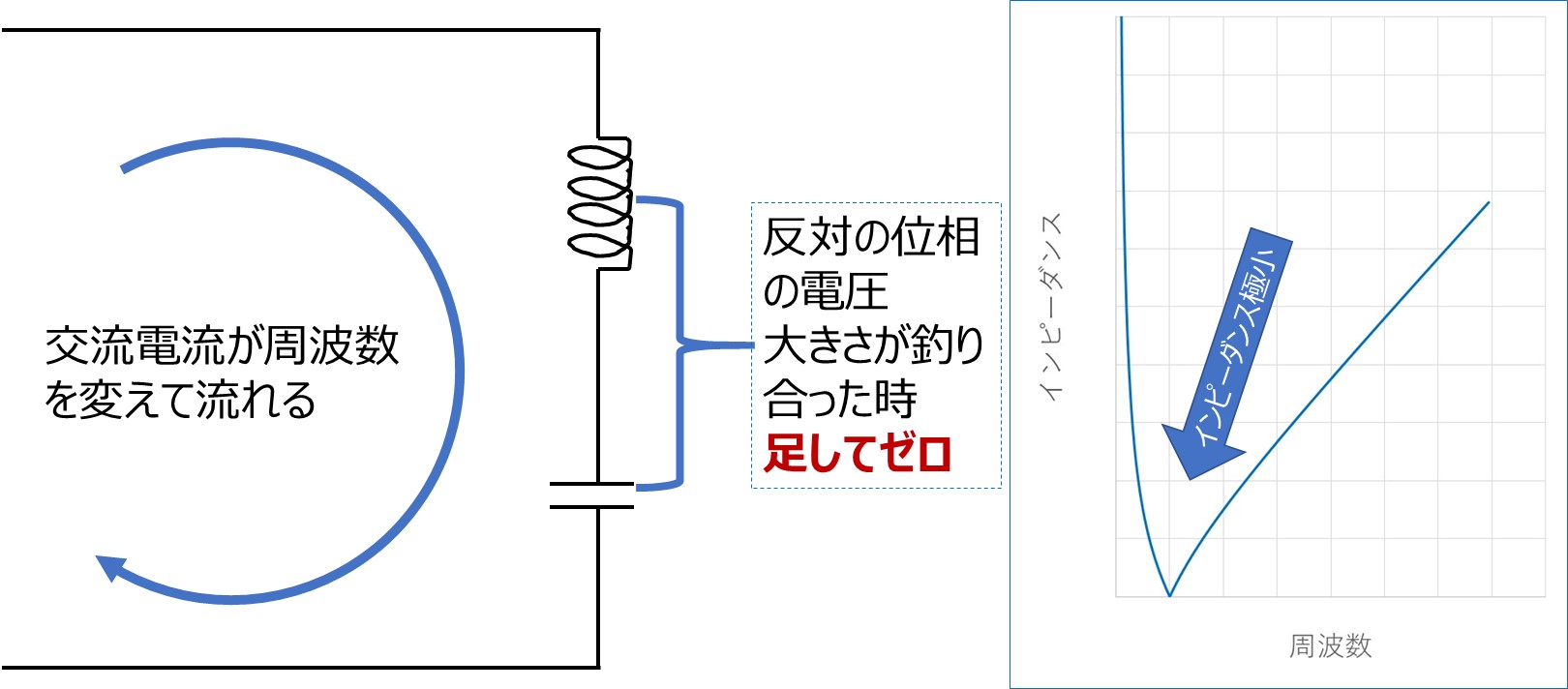
In this circuit, the waves of current flowing through each other cancel each other out completely at the pinpoint where the impedance of C and L is balanced. Although current flows through the element, it is self-contained and no current comes in from the outside.
The impedance seen from the outside is maximum = infinity because even though there is a voltage, no current flows.
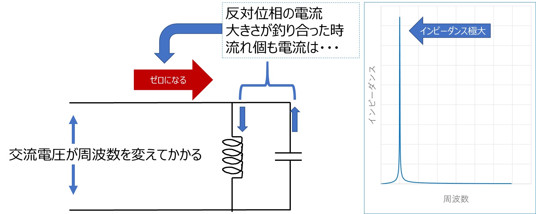
In both cases, the minimum or maximum occurs at a frequency of f = 1/(2π√(LC)) (Hz). Actual components and circuits have resistance components in various places, so they exhibit slightly milder characteristics than the examples above, but impedance still reaches a pinpoint minimum or maximum. This phenomenon, where current suddenly becomes easier or harder to flow at a specific frequency, is called electrical resonance (some people may not quite understand the word resonance, but I am one of them). This phenomenon is used as a filter in circuits that allow or block only specific signals to pass.
Now, to make things more complicated, there is another type of phenomenon called electrical resonance. Personally, I think this is a more appropriate name for resonance and is easier to imagine, but I'll move on to that one.
② Resonance due to reflection
The column briefly touches on the effects of characteristic impedance and reflection in the section titled "Are 'Floating structure' and 'high-speed transmission' contradictory requirements?" The figure below is a reprint of the figure used in the section titled "Why is reflection a problem?" in that column.
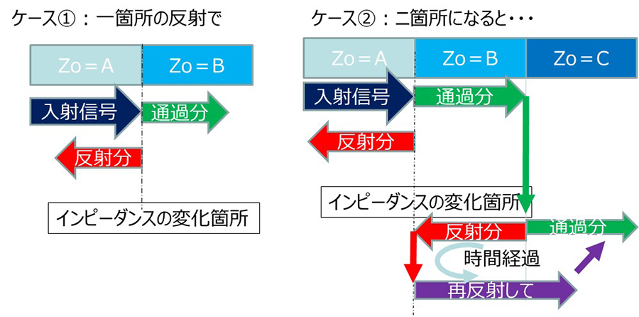
At the time, the problem was that signals that were reflected and overlapped over time were considered "noise."
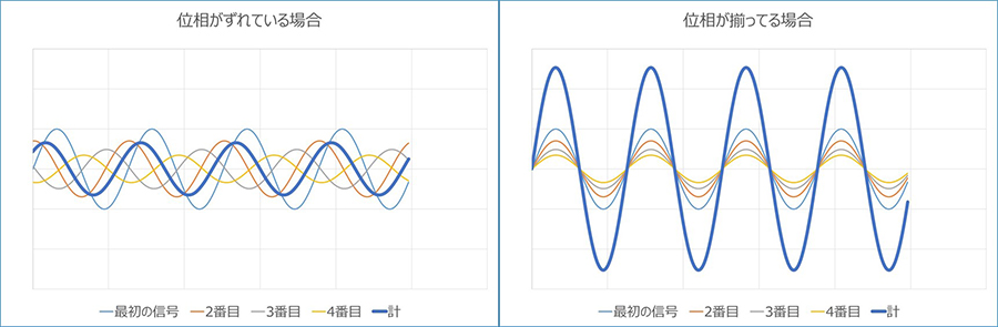
So what happens if a repeating signal is received as is?
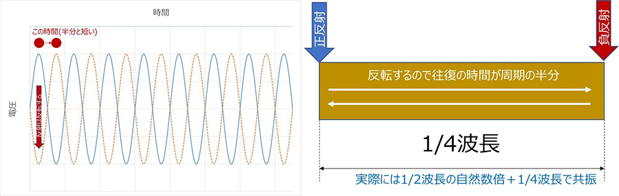
The following is a simplified comparison of the sum of four waveforms that gradually get smaller and shift in phase, and the case where the waveforms gradually get smaller but happen to be perfectly aligned in phase. On the left, the first waveform and the shifted ones become smaller and are combined. On the right, the first waveform is simply enlarged and combined.
For example, in the diagram adapted from the first question, "Why is reflection a problem?", if the time it takes for the wave to travel around and the time between the crests of the wave are aligned, they would likely reinforce each other (in reality, there is also a type of reflection that is reversed, called negative reflection, but consider this to be the case for positive reflection).
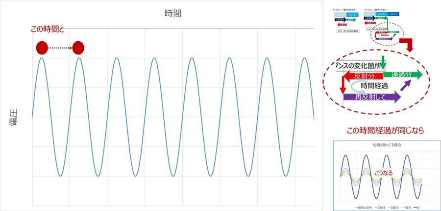
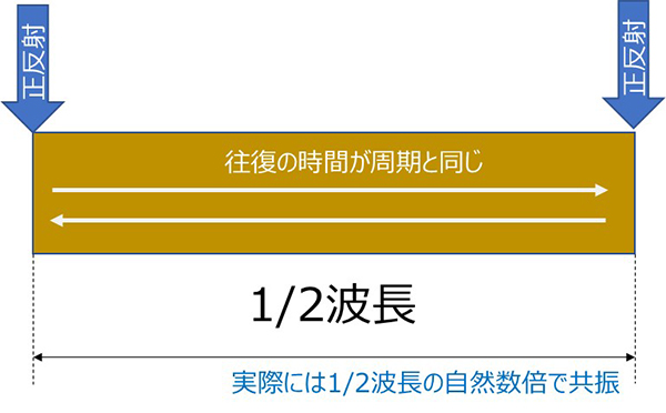
In fact, when a signal line of finite length is reflected specularly at both ends, if the wave period and the time it takes for the signal to travel from one end to the other are the same, the phase of the AC wave (sine wave) caused by the repeated reflections will be aligned, and the superposition will interfere and become stronger. The length of the line = the length it takes to travel one way for half the period, so it can also be said to be half the length of the wave = 1/2 wavelength.
In fact, when a signal line of finite length is reflected specularly at both ends, if the wave period and the time it takes for the signal to travel from one end to the other are the same, the phase of the AC wave (sine wave) caused by the repeated reflections will be aligned, and the superposition will interfere and become stronger. The length of the line = the length it takes to travel one way for half the period, so it can also be said to be half the length of the wave = 1/2 wavelength.
The formula for calculating the wavelength is as follows:
λ = (C/√ε) / f
λ = wavelength (m) C = speed of light = 3.08 × 10⁸m/s εs = (equivalent) relative dielectric constant around the line f = frequency (Hz)
In air (strictly speaking, in a vacuum), it is about 6000 km at 50 Hz, about 300 km at 1 KHz, about 3 m at 100 MHz, finally about 30 cm at 1 GHz, and about 12 mm at 25 GHz. 1/2λ is half of each of these. If the surroundings are filled with a substance other than air, it will be shorter than this. For plastics, it is about 80% to 1/3 depending on the material.
However, if the reflection is negative on only one side, the wave will be reversed, so the frequency where the line length corresponds to 1/4λ will be the resonant frequency.
This applies to either side, but only to one side. When both ends have negative reflection, the frequency at 1/2λ is the resonant frequency, just like when both ends have positive reflection. Think of it as a mental exercise. Incidentally, when the characteristic impedance of the outside of the line is lower than that of the line, there is a positive reflection (total reflection with a short circuit), and when it is higher, there is a negative reflection (total reflection with an open circuit).
Harmful effects of resonance caused by reflection
Now, this is the second type of electrical resonance – resonance due to reflection – but what does this phenomenon bring about?
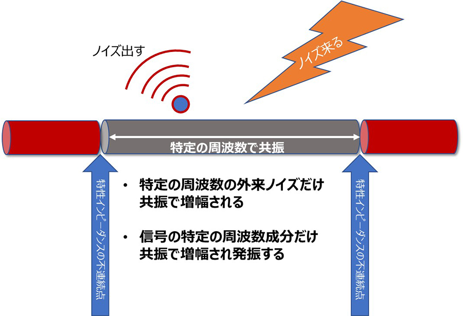
The phenomenon of resonating and amplifying only specific frequencies can be effectively used in antennas and filters, but here we will consider the negative aspects. Let's look at a line sandwiched between discontinuities in the characteristic impedance. Reflections occur at both ends of this line, causing resonance at a specific frequency.
When a signal flows, resonance occurs only at certain frequencies, making it easier to emit. Also, even if external noise of a certain frequency is small at first, it can reach a level that cannot be ignored due to resonance. By the way, it is surprisingly difficult to know in advance whether positive or negative reflection will occur at an impedance discontinuity. Therefore, when designing wires and wiring lengths, it is best to avoid lengths that are N times 1/2λ or +1/4λ for frequency bands of particular concern, such as wireless signal bands that may be flying around in the vicinity or the main wave number of signals flowing through the line.
This is more than 20 years ago, but one of the engineers I worked with in my previous job had created and used a calculation spreadsheet in Excel that would allow him to input various factors to "determine the cable length that would not cause resonance by taking into account tolerances" as a countermeasure against EMI (although when I asked to have the Excel spreadsheet, he refused, saying "It's just know-how..."). I also heard about a case where a device suddenly failed an EMI test after changing a cable to connect it, and although the cable's shielding was suspected to be defective, it was later discovered that the difference in the dielectric constant of the wire had caused the cable to have exactly the resonance length of the main frequency. In both of these cases, the problem occurred over a period of several meters or centimeters.
On the other hand, as I wrote in the column "Are 'Floating structure' and 'high-speed transmission' contradictory requirements?", what happened in the "km" unit in the telephone communication era started happening in the "m" unit when communication speeds increased to "Mbps", and now in the "Gbps" era, it is happening in the "mm" unit. If we were to worry about the "mm" unit in the current era of faster signals, we would not be able to use anything if we avoided the resonance length for everything. Therefore, it is very important to match the characteristic impedance of connections between lines and parts and inside parts, and in addition, shielding measures and installation processing are also important. (This is briefly touched upon in the "Options to improve connector reliability" section under "What is a connector" on the site).
This second phenomenon of electrical resonance is creating an increasing number of issues that we as connector manufacturers have to address in recent years.
summary
This time, I started by looking at the word resonance, which is used in multiple situations, and the confusion that arise from the situation, and then explained the two types, mechanical and electrical.
For us connector manufacturers, both mechanical and electrical issues bring about daily challenges that we must address and take measures against. We strive to learn and think carefully about these issues, not just about their disadvantages, but also about how they can be used effectively, so that we can create a succession of products that will be useful to you!