
- Top
- Technical Info
- column
- What is the relationship between data rate, carrier frequency, and connector?
What is the relationship between data rate, carrier frequency, and connector?
Wi-Fi signals are in the 2.4GHz and 5.0GHz bands. But when you connect, the data speed is only 100Mbps. It's a little confusing.
I have talked about frequencies and data rates in this column, but the circumstances seem to be different from what I discussed there.
In the "Finally" section of the column:
For example, in the case of a wireless connection that passes modulated signals (coaxial connectors are used, etc.), excellent (i.e. stable) performance is required in the "narrow band" of the "very high frequency" that is the carrier frequency.
I've only touched on this briefly, so please take a look if you're interested.
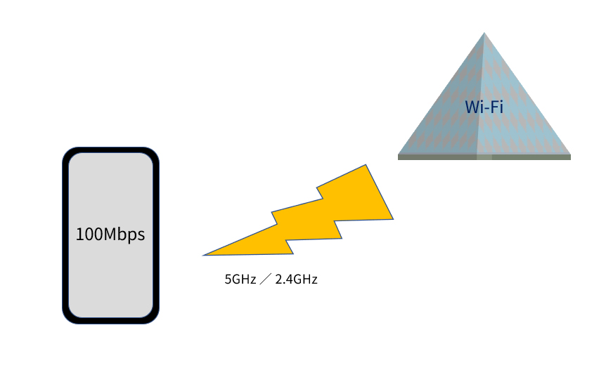
Figure 1 What are wireless frequencies and data rates?
This time, I would like to explain about high-speed signals such as those transmitted wirelessly, and what kind of performance is required of connectors.
Although I graduated from an engineering school a long time ago, as a public relations officer of a connector manufacturer, the topic is a bit too much for me, but the topic of "modulation" is unavoidable. That's why, because I'm not an expert, I've decided to explain it roughly to the best of my understanding, avoiding technical explanations as much as possible, while also including what I've studied in a cursory manner. If you want to know more technical details, there are many websites that explain it, so I hope you'll take a look at those as well.
I would like to start by talking about the world of modulation, which is a little removed from connectors, and finally land on the question, "So, what about connectors?"
What is Modulation?
Roughly speaking, modulation is "putting a signal waveform/information onto an electrical wave of a frequency that is easy to send as a radio wave." Electrical waves that are easy to send as radio waves are called carrier waves.
Also, since the modulated signal cannot be used as is by the other party, a process called "demodulation" is also performed to extract only the signal that was intended to be sent.
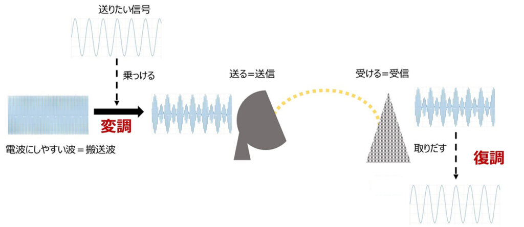
Figure 2 Modulation → Transmission → Reception → Demodulation
This is how modulation (and demodulation) makes it possible to send and receive signals using wireless and optical communication without using electric wires. In the case of Wi-Fi, which I mentioned at the beginning, 5GHz or 2.4GHz is the carrier frequency, and 100Mbps is the data rate of the signal carried on it.
Wi-Fi modulation is what is known as digital modulation. Before talking about digital modulation, I would like to first explain analog modulation.
Analog Modulation
There are three types of analog modulation:
- AM modulation/amplitude modulation
- FM Modulation/Frequency Modulation
- PM modulation/phase modulation
Of these, I think many people have heard of AM and FM as "AM radio" and "FM radio." But maybe that's not the case these days? Perhaps so-called Internet radio is more familiar. By the way, the reason we refer to it as radio is just another example of a system that "remains famous even after a change in format," just like how we still say "turn the channel" when changing the channel on a TV, or how we still say "renchin" when heating something in the microwave (though now the sound it makes when it's done is more like "ren-pee").
Getting back to the topic at hand, let's start with AM modulation. As the name suggests, it is a method of superimposing a signal by changing the amplitude (size) of the carrier wave. When you make it into a calculation formula, it includes various coefficients such as the modulation depth, and it becomes quite complicated. We won't go into the details here, but there are technical explanations on various websites, so please take the time to search for them.
Now, in the diagram, I deliberately chose a complicated waveform for the "signal I want to send" to create a modulated wave.
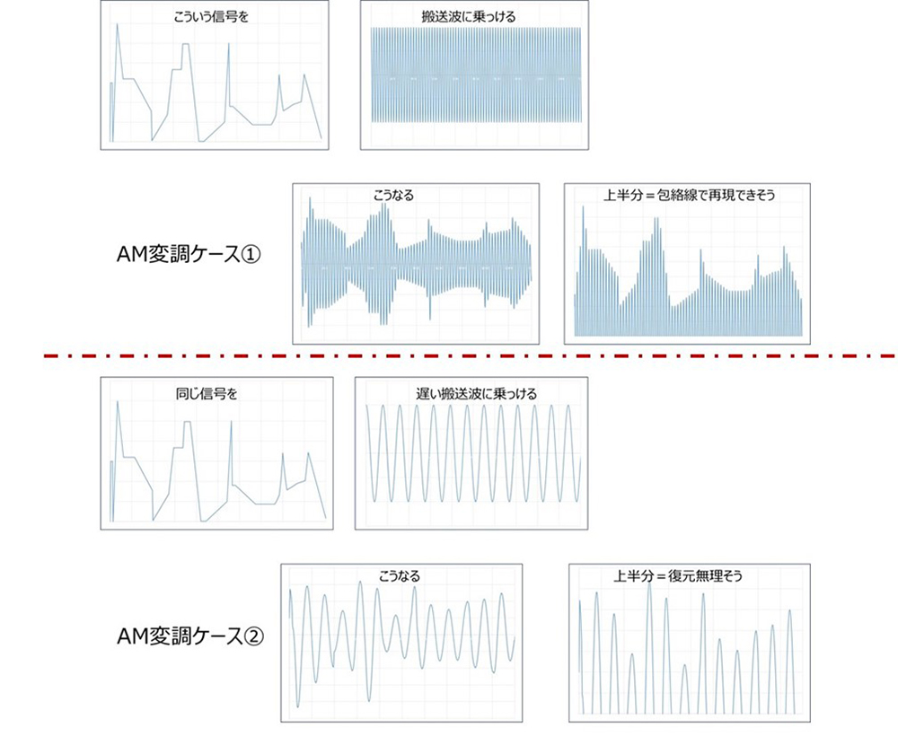
Figure 3 AM modulation and carrier frequency
What I want you to see here is the reproducibility of the original signal waveform. (I used a slightly complicated waveform for this purpose.)
In the upper row, "AM modulation case ①," it looks like we can reproduce the original waveform quite well by taking the envelope of the modulated waveform.
On the other hand, in the lower row, "AM Modulation Case ②", the frequency of the carrier wave is lowered. Then, the waveform after modulation is just floppy and has no trace of the original waveform. It can be seen that the more intense the movement, the less complete it is.
In other words, in case ②, the carrier frequency cannot keep up with the amount of information you want to send. As a result, the original information is lost during modulation. I explained this using the example of AM modulation because it is easy to understand visually, but in order to send as much information as possible, the carrier frequency must be increased.
This is also true for FM/PM modulation, which will be explained next. In other words, the frequency of the carrier wave needs to be much higher than the frequency (component) of the signal you want to send.
Furthermore, the information content efficiency per carrier frequency is higher with AM modulation than with the other two methods. However, because AM modulation reproduces the signal you want to send by changing the propagation strength, it is inevitably vulnerable to noise.
This is where FM modulation and PM modulation come in. These methods change the frequency and phase of the carrier wave "according to the signal you want to send" rather than its amplitude, and although they reduce the efficiency of information content, they are more resistant to noise that tends to occur as a result of affecting the amplitude.
Now I have prepared diagrams for sending simple signals, so let's take a look at each waveform.
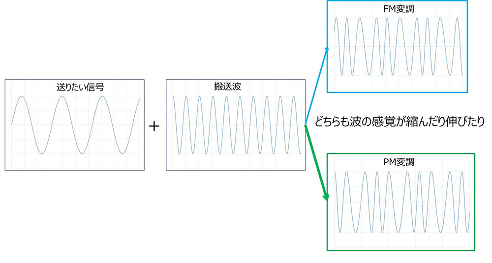
Figure 4 FM and PM modulation waveforms
I don't really understand the difference... FM and PM are like brothers, and it's a little hard to tell them apart. (I also had trouble with modulation when I was a student.)
Due to the frequency range, PM is slightly more efficient (though not as efficient as AM), but the difference seems to be that the circuits tend to be more complicated. However, while FM has seen the light of day on radio, PM is not heard much. In fact, this method is actually flourishing as an application to the next digital modulation.
Digital Modulation
Nowadays, people often have the image that information society = digitalization. The vague impression is that digital is richer in information than analog. While there is nothing wrong with the results that are produced, in the world of electrical signals, analog has much more information, or requires much more information to reproduce. To put it more simply, all electrical signal "waves," even those for digital use, are analog in the sense that they are continuous (not discrete). Analog reproductions tend to be ambiguous, and it is very time-consuming to reproduce correctly. With digital, information is summarized to the essentials, making it easier to reproduce and highly available.
This has gotten a bit conceptual, but essentially, there are efficient modulation methods that are unique to digital.
In the previous section, we wrote that "the carrier frequency must be much higher than the frequency (component) of the signal you want to send," but the situation changes with digital modulation if you replace frequency with data rate. To give you an idea of what it is, let's try modulating a digital signal with AM modulation, which is used to send an analog signal with a high amount of information.
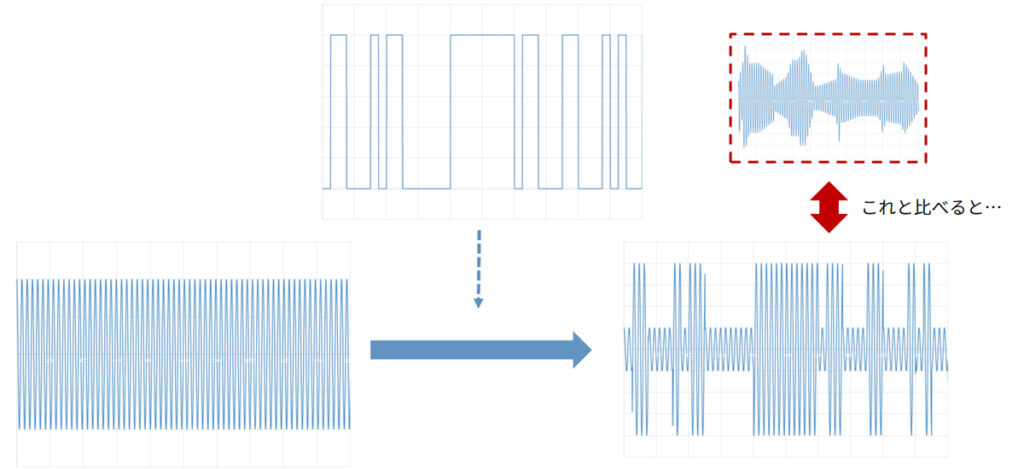
Figure 5. Trying AM modulation of a digital signal
If we try to modulate a digital signal using AM modulation, it will look like the bottom right side of the figure.
Compared to the analog AM modulation example, doesn't this seem a bit wasteful?
When transmitting signals using analog modulation, the key to signal quality is how closely the waveform shape can be reproduced at the destination.
The parts that we try to reproduce include, for example, small details that were not "intended" in the original digital signal.
So, sending digital signals using an analog approach seems a bit wasteful.
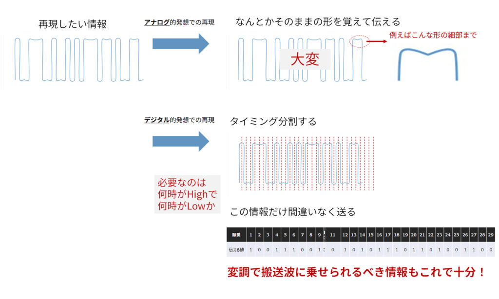
Figure 6 Analog and digital reproduction of a digital signal
This led to the development of a modulation method unique to digital - digital modulation.
Initially, there were methods such as AKS (Amplitude Shift Keying), which does not emit a signal when the value is zero and only emits a signal when the value is one, and FKS (Frequency Shift Keying), which assigns two frequencies to 0 and 1.
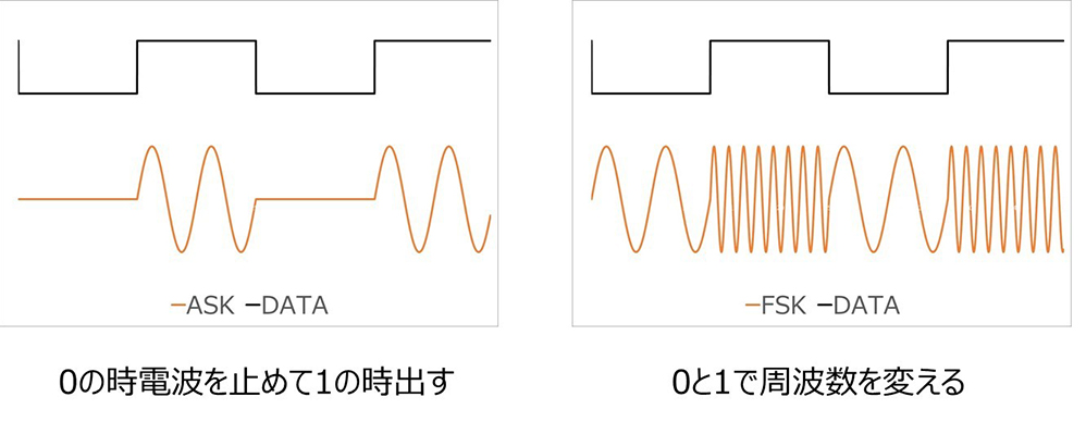
Figure 7 Early digital modulations ASK and FSK
Compared to analog modulation, this is much simpler.
Although this is a much simpler solution, it seems like the amount of data that can be sent per carrier frequency is small. In addition, ASK only requires switching, but FSK requires two types of waves.
For this reason, in order to make the signal a little more complex and increase data efficiency, phase modulation was used, which had not seen much use in analog systems.
The method used in digital modulation is called PSK (Phase Shift Keying).
This is an image of QPSK (Quad Phase Shift Keying), which uses four waves with different phases to transmit two bits per symbol. (Two wavelengths, one symbol.)
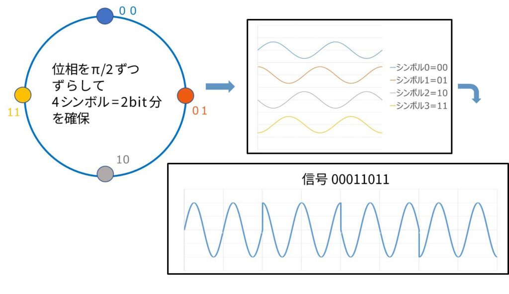
Figure 8 QPSK
The image shows a somewhat awkward waveform, but it would allow for much higher data rates to be transmitted at a given carrier frequency.
Furthermore, a method called QAM can be used to send large amounts of data by combining multiple amplitudes and multiple phases, which is a combination of ASK and PSK. Since it combines phase modulation and amplitude modulation, it can really increase data capacity. This is possible only with digital, which has a simple reproduction.
The diagram shows a method called 16QAM, which is also used in Wi-Fi. (To simplify the diagram, we have used 16QAM as an example, but 64QAM is also used.)
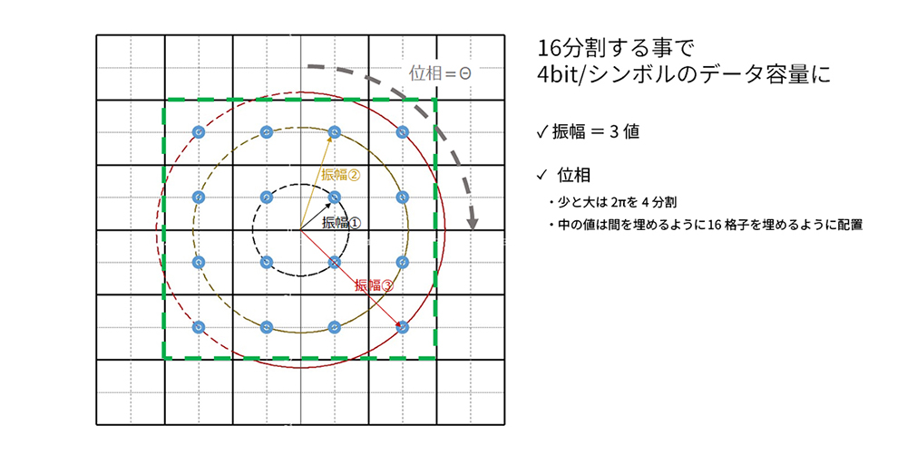
Figure 9. 16QAM symbol polar coordinate display
If we plot the amplitude and phase of 16QAM on a polar coordinate system, it looks like the figure above.
The 16 blue circles are called symbols used in transmission. By having 16 different symbols, 4 bits of data can be sent per symbol. In other words, each symbol corresponds to a value from "0000" to "1111". Since this is a polar coordinate system, the distance from the center is the amplitude, that is, the further above the outer circle it is, the larger it is.
On each circumference, the phase shift is zero in the vertical upward direction, and the further to the right you go, the more the signal will shift/lead in phase by that angle. This is getting quite complicated, isn't it?
The amplitude is divided into three. One thing to note is that the phase division on the same amplitude is not modulated with an equal phase difference for all amplitudes, but is a slightly unique division. As a result, the symbols are placed in the "center of each of the 16-division grids." The closer the distance between symbols on the polar coordinate system is, the more difficult it is to distinguish them, so it seems that this shape is chosen to ensure that each symbol is well-distant.
By the way, as explained in the other articles "Frequency and Data Rate" and "Frequency Distortion and Coding" in this column, NRZ supports data rates twice the Nyquist frequency, and PAM4 supports data rates four times the Nyquist frequency. Although it is not possible to uniformly compare wireless modulation with direct signal transmission, it appears that 16QAM has a data rate vs. frequency efficiency comparable to PAM4, "despite modulation."
There are also 64QAM and 256QAM, so it seems like it would be possible to send data with incredible efficiency. However, as the data gets more complex, it naturally becomes more difficult to reproduce it on the receiving end.
On the other hand, there is a definition of how much data is delayed relative to the carrier bandwidth, called spectral efficiency, and it is expressed in units of bits/s/Hz. Bandwidth, which I will explain a little later, is the "range" that is expanded to the modulation of the carrier frequency. In addition, there is something called the Shannon-Hartley theorem, which states the maximum amount of information that can be transmitted without errors in a noisy environment as given by the following formula, and this holds true regardless of the encoding method.
Maximum communication capacity = Bandwidth × log 2 (1 + signal power / noise power)
As the noise gets louder, the value inside the parentheses around log2 gets smaller and smaller, eventually becoming 1. Since the logarithm of 1 is always zero, the maximum communication capacity will also be zero.
On the other hand, if the signal power is large enough, signal transmission can be performed more efficiently. Unfortunately, the bandwidth is the bandwidth, not the carrier frequency, so although it is easier to increase the bandwidth with a higher carrier frequency, it is difficult to directly imagine the data rate.
So, let's take a look at the actual data rates for wireless communication using examples of each generation of Wi-Fi. (4-7)
| Wireless LAN Standards | Communication speed (maximum) | Frequency band | Modulation Method |
|---|---|---|---|
| Wi-Fi 7 | 46Gbps | 2.4GHz/5GHz/6GHz band | 4096QAM |
| Wi-Fi 6 | 9.6Gbps | 2.4GHz/5GHz band | 1024QAM |
| Wi-Fi 5 | 6.9Gbps | 5GHz band | 256QAM |
| Wi-Fi 4 | 300Mbps | 2.4GHz band/5GHz band | 64QAM |
Wi-Fi, which was previously thought to be around 10Mbps, has also become much faster.
The Wi-Fi example cited at the beginning was 100Mbps because it was an example of sending 100BSE-T over Wi-Fi, but it is now possible to send up to 1000BASE-T, and I think many people are actually using it. (I live in an apartment complex with a base line that is only 100Mbps at most, so I haven't been able to benefit from it...)
Modulation methods are also becoming increasingly more efficient, going from 64QAM (6 bits/symbol) to 256QAM (8 bits/symbol) to 1024QAM (10 bits/symbol) to 4096QAM (12 bits/symbol).
In this way, with modulation methods unique to digital, the amount of data that can be sent using the same carrier wave is steadily increasing.
So what kind of connector is needed to connect these modulated signals?
Modulated Waves and Connectors
Where the modulated wave passes
If we roughly divide wireless communication using modulated waves into blocks, it would look like the diagram below.
First, the transmitting side creates a modulated wave from the carrier wave and the signal to be sent, then amplifies and transmits it.
On the other hand, on the receiving side, after receiving the signal via the antenna, unnecessary frequency (out-of-band) noise is cut out, the signal is amplified, and then demodulated.
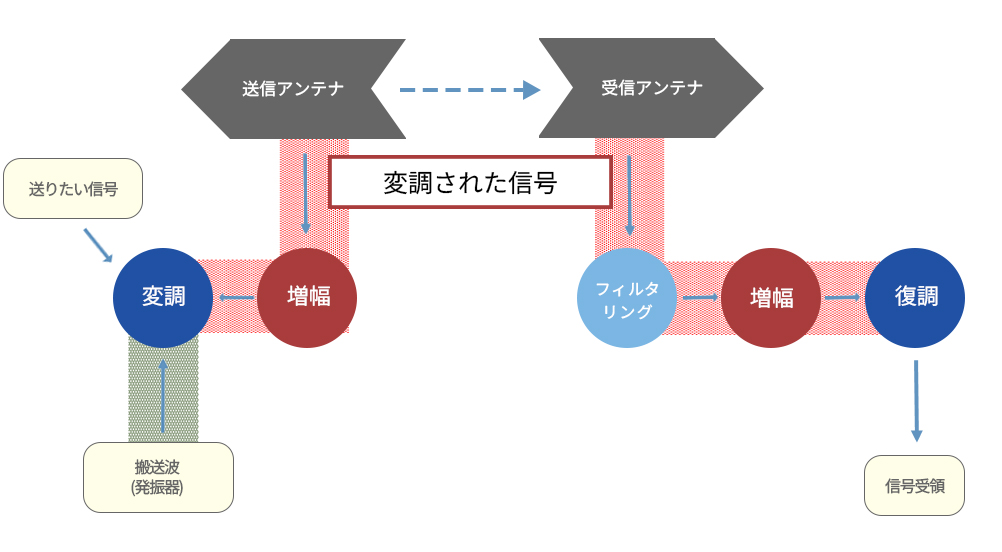
Figure 10. Rough outline of wireless transmission block and where the modulated signal passes
In this case, the red shaded area is where the modulated signal passes through "by wire." If there is an electrical connection here, an appropriate connector is used. Incidentally, the carrier wave is a signal with the main frequency of the modulated wave, so the transmission path configuration can easily be shared with the modulated wave.
Frequencies to watch out for in modulated waves
The frequencies that should be considered for transmission paths and connectors in digital transmission are explained in the previously cited "Frequency and Data Rate" and "Frequency Distortion and Coding" sections, including background information. For normal digital signals, a wide range must be considered from low to high relative to the Nyquist frequency based on the data rate. Also, continuity of performance is important; for example, if the characteristics are "too good" at a lower frequency than the Nyquist characteristics, this can lead directly to waveform distortion.
So what about wireless communication using modulated waves? Does it depend on the data rate? I'm sure there are many of you who have read this far who are thinking, "No, it's not!"
That's right. In wireless communication using modulated waves, the frequency that the connector should take into consideration is determined by the carrier frequency, regardless of the data rate. Of course, the required performance can be stricter, as can be seen from the above-mentioned Shannon-Hartley definition, but the frequency that you should be concerned about is determined by that of the carrier.
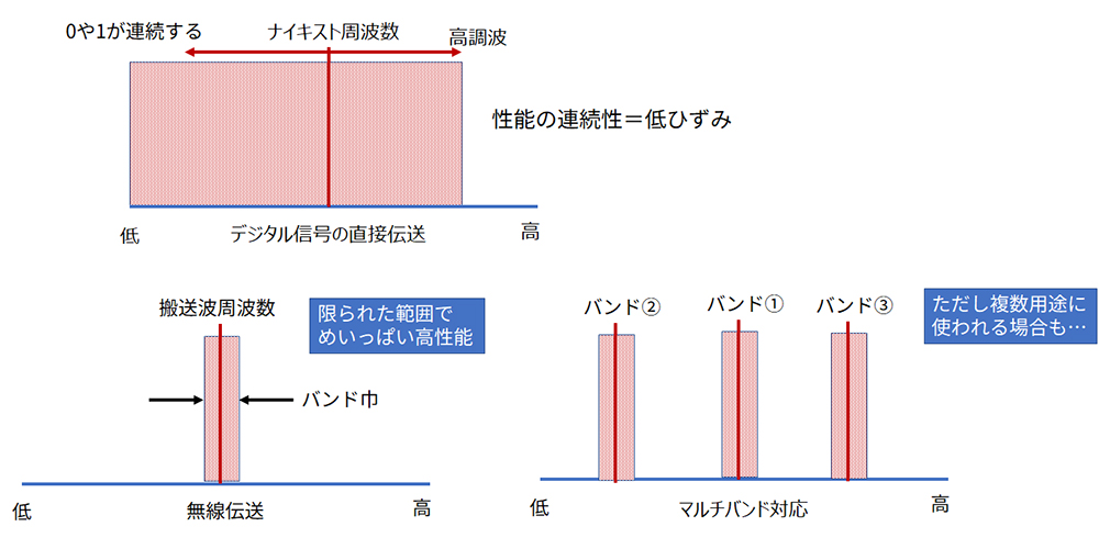
Figure 11. Wireless communication/modulation waves Frequencies to consider
However, since there will be a certain bandwidth when modulating, it is necessary to consider the carrier wave ±α frequency range. If the application is clearly defined, the best connector will be the one with the highest performance within this limited range.
On the other hand, when considering the requirements for connectors, they need to be versatile to a certain extent. Also, for devices that support multiple bands, it would be troublesome to use different types of connectors for each band. Therefore, connectors that can provide high performance over a fairly wide range of bands are preferred.
If it's single-ended transmission, then it's a coaxial system.
The modulated signal is essentially single-ended.
After being picked up by the antenna, in some cases a single-ended to differential conversion is performed using something like a chip balun as an EMC measure, but in most cases it is used in its single-ended form.
As explained in the column "Reasons for differences in connector performance between single-ended and differential transmission," coaxial connectors/cables continue to be used for single-ended transmission, so when it comes to single-ended, coaxial connectors/cables come into play.
VSWR or Return Loss?
Coaxial connectors used in wireless communication are required to have many characteristics, but one particularly important characteristic is VSWR. VSWR is basically the same as return loss, and it is possible to convert it unambiguously using a formula. The definitions of each are listed in the links, but the conversion formula is as follows.
Return Loss (dB) = – 20 × log (VSWR – 1) / (VSWR + 1)
VSWR is the preferred performance parameter for coaxial connectors, which have been developed especially for wireless communications, because it is much easier to visualize, calculate, and compare antenna performance in VSWR format than in return loss format.
On the other hand, in the world of digital transmission, return loss is more familiar and easier to handle, but even when coaxial connectors enter that world, the performance listed in the relevant section is often VSWR.
We also use FAKRA connectors as part of our "Onboard Coaxial Camera Solution."
On the relevant page, we also state, "We will work with FAKRA connector manufacturer to evaluate and verify the combination of our rear case and PCB connector, and guarantee the overall Mating and transmission." Incidentally, when we asked for the reflection characteristics in the initial exchange, the performance presented was in VSWR, and moreover it was a graph "image," so our engineers who received it seemed to freeze for a few tenths of a second. (Of course, we would deepen our mutual understanding in subsequent exchanges.)
I've digressed a bit, but these points, apart from the frequencies that you need to be concerned about, also suggest differences in the "things that need attention" when it comes to connectors used for wireless communication and direct digital transmission.
How strict is it?
The VSWR of coaxial connectors for measuring instruments can be 1.05 or less, but for wireless communication applications the maximum value is often 1.2 to 1.5 in the specified band, with most being 1.3 or less. Let's compare this with the return loss (Sdd21) of some differential transmission standards that directly transmit digital signals.
For more information on our standards, please also refer to "Definition of supported data rates for Board to Board Connectors" and "Definition of supported data rates for FPC/FFC connectors," which explain the background to the settings.
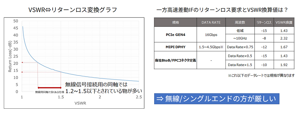
Figure 12 Differences between operational interfaces and reflex requirements
If you check this, you can imagine that the reflection requirements for connectors for wireless communication are strict for differential IF. This is one of the reasons why I mentioned earlier that it is "highest performance possible within a limited range."
In addition, although we have mentioned that most products have a VSWR upper limit of 1.2 to 1.5, in the design of actual equipment, higher performance is preferred within the range that satisfies the function. There is also degradation in parts other than the connector, and especially on the receiving side, you want to quickly demodulate the exhausted signal that was finally picked up by the antenna and sent over the radio while preventing even a little degradation. The same goes for performance related to signal quality other than VSWR.
Connector structure
As explained in the "Single-ended transmission, then, is it a coaxial system?" section of this column and in the "Reasons for differences in connector performance between single-ended transmission and differential transmission" column, single-ended transmission requires a connector with a structure suited to single-ended transmission. Also, when connecting boards together, there are cases where more functionality than simply "connecting only the parts you are responsible for" is required, such as ease of assembly and elimination of mechanical concerns when connecting multiple boards.
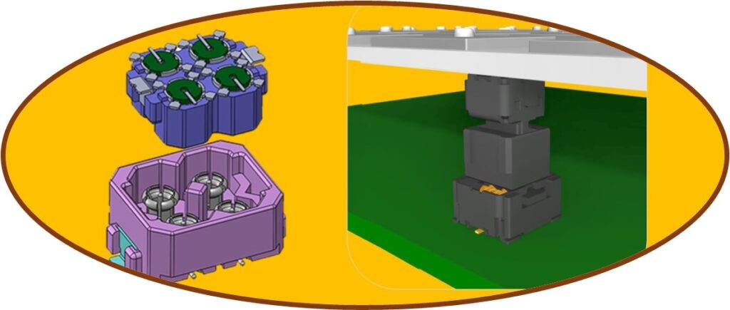
Therefore, as explained in the column, "deviation from and approach to the coaxial structure" is the key to connector structure. The "Floating structure coaxial connector, which allows the connector axis to shift using a cone-shaped receptacle" cited in the column was developed for exactly this purpose.
When designing a structure, the most important thing is to have a stable and continuous characteristic impedance down to the smallest detail. The relationship between structure and characteristic impedance is also explained briefly in "Although the product forms are different, are "Floating structure" and "high-speed transmission" contradictory requirements?", so please refer to that as well.
Our specialty is board-to-board connections, but communication devices use a large number of coaxial connectors to connect antenna boards. In the automotive market, multiple coaxial connections are required for multi-band support, such as shark fin antennas. As of September 2022, we have not yet launched any products that support these, but we are working hard to develop products with new added value based on both coaxial and pseudo-coaxial concepts.
When that time comes, we believe we will be able to add new applications to the "Industrial Equipment Connectors" and "Automotive Connectors" sections in the "Connection Proposals" section of our website.
lastly
Thank you very much for staying with us until the end.
The theme this time was more complicated than ever before. I myself had questions and only vague understandings of many things, so I had to review and research a lot of new information. It was a little difficult, but I learned a lot.
There are still many difficult points, and there may be better ways to interpret it, so I would appreciate it if someone with more knowledge could comment. As for related products, rather than being our current specialty, they are areas in which we would like to focus in the future while taking advantage of our strengths. Please look forward to the release of new products in the future!