
- Top
- Technical Info
- technical note
- Definition of supported data rates for Board to Board Connectors
Definition of supported data rates for Board to Board Connectors
Determined from the S parameter at differential 100Ω, the lowest value among the following is the recommended transmission speed/Data Rate
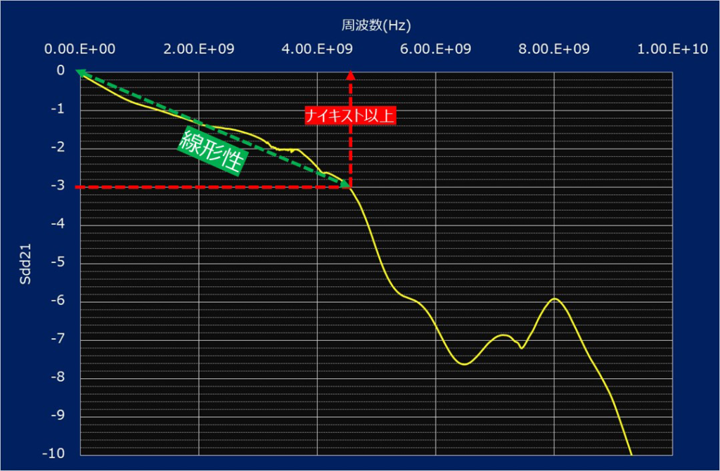
- Insertion loss = Sdd21 has sufficient linearity up to the Nyquist frequency and does not fall below -3dB
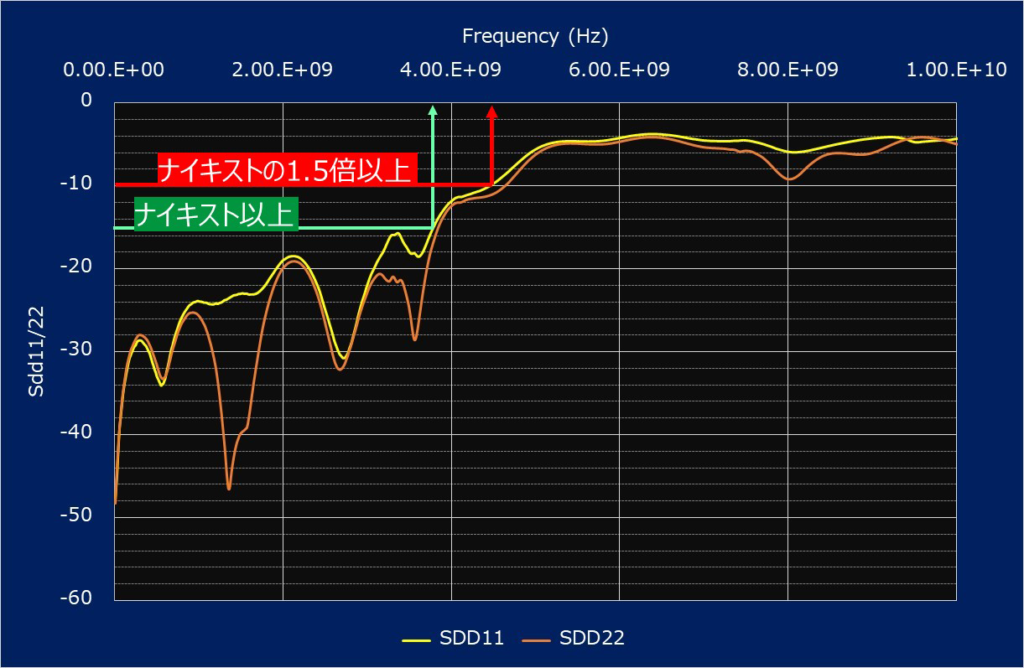
- Return loss = Sdd11/Sdd22
- Do not exceed -15dB to the Nyquist frequency
- Do not exceed -10dB up to 1.5 times the Nyquist frequency
*Unless otherwise specified, the S-parameters were obtained with those recommended in the product drawing, and the mounting part (ex. SMT board side pad, etc.) for
*If compatibility with or compliance with an interface standard, etc., is indicated, the requirements of that standard are met.
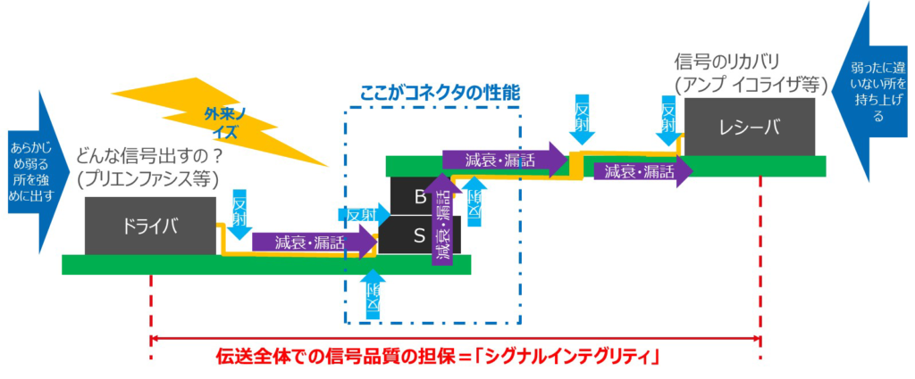
Connectors in signal integrity
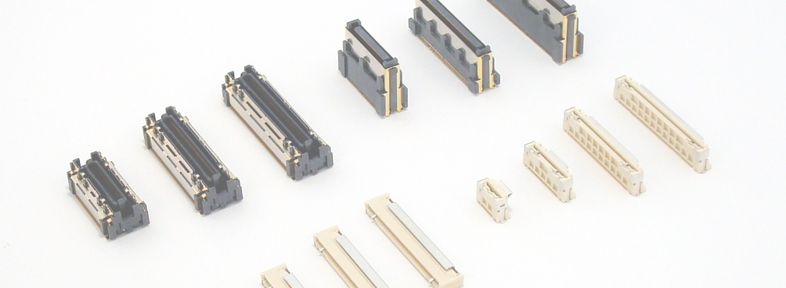
Connectors are passive products that provide a "connection" function, taking a portion of the transmission margin in the context of "signal integrity." Except for cases where the "share" of each component is defined by standards, the exact characteristics required vary depending on the customer's system configuration. Ultimately, the connector is selected after simulations using characteristic models and detailed data verification, followed by evaluation of the actual product. In other words, except for standardized products, the expression "Gbps-compatible connector" is not necessarily accurate. However, we understand that information such as "compatible data rate" is extremely useful, even as a rough guide, during the initial customer consideration phase. Therefore, IRISO has defined "compatible data rate" as a reference value for our recommended values, based on our experience supporting customers and our track record in evaluating and designing high-frequency products, and has begun assigning it to each product group. In doing so, we keep the following points in mind.
- Clarify and disclose the definition and reasons for fairness
- The idea and "value" must be reasonable for actual use
- It is easy for the customer to attach the hit when incorporating it into their own system
Differential 100Ω/S-parameter based definition
The data rate definition was performed with the most requested differential 100Ω, and was defined based on the mixed-mode S-parameters, which are the most popular parameters for passive components for high-speed transmission. In addition, because it depends on the customer's usage environment, crosstalk is not taken into account, and a single lane is defined. To avoid complication, the definition is based only on differential transmission and reflection characteristics. As a general rule, we use products that are mounted on our own printed circuit board, including soldered parts to the circuit board.
(For crosstalk and common mode conversion, we also provide individual data and conduct evaluations, so please contact us.)
Pass-through characteristics: Sdd12/21
The pass characteristics required for transmission lines are actually various due to processing such as emphasis and equalizing, and there are various discussions on harmonics (transmission margin vs. noise source, etc.). Therefore, our definition is easy to understand, and based on the basics, in NRZ transmission, it is -3 dB or less at the Nyquist frequency (Data Rate/2), which is the main frequency, and has sufficient linearity.
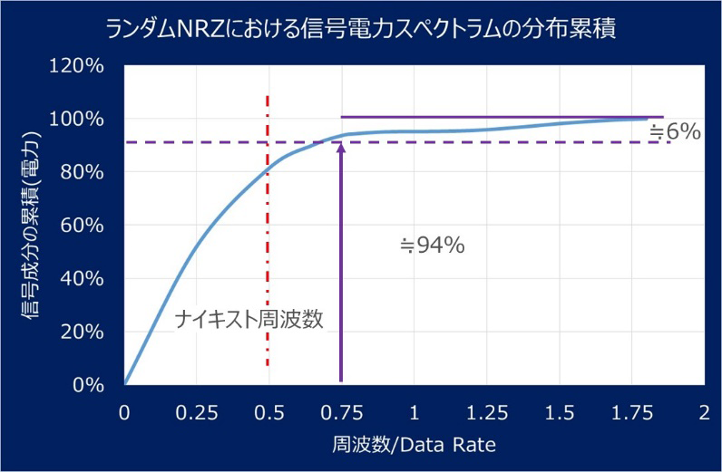
Reflective properties: Sdd11/22
Reflection properties must be considered in terms of "noise generation" as well as signal transmission. Therefore, according to our company's regulations, in addition to not exceeding -15 dB at the Nyquist frequency, it is up to 1.5 times the Nyquist frequency (75% of Data Rate = right figure), which is calculated to cover the main spectrum in NRZ random transmission. -10dB = electric power, and it is stipulated that it should not exceed 10%.
This is a stricter regulation than recent transmission standards, such as PCIe CEM after Gen3.
Data rate supported by the product
In cases where both the transmission and reflection characteristics mentioned above are satisfied, that is, the "strictest" data rate required from each is the recommended compatible data rate. In reality, with Board to Board Connectors, the reflection characteristics are stricter and the transmission characteristics often have significantly better performance (lower loss) than the recommended data rate shown.
In addition, if there is compliance with various standards (ex. PCIe GEN3.0), it may be listed together, and there may be a gap with the recommended data rate. Even if the recommended data rate in our standard is lower than the standard transmission speed, it can be used because it satisfies the required performance.
High-speed transmission quick reference
Stack 0.40mm Pitch
| Supported data rate Applicable Data Rate |
Stack Height | plug | Socket |
| 12.1Gbps | 2.00mm | 11010B | 11010S |
| 11.8Gbps | 3.00mm | 10126B | 11007S |
| 8.7Gbps | 3.50mm | 10126B | 11007S |
| 8.1Gbps | 3.00mm | 10126B | 10126S |
| 8.0Gbps | 4.00mm | 10126B | 11007S |
| 7.0Gbps | 3.50mm | 10126B | 10126S |
| 6.5Gbps | 4.00mm | 10126B | 10126S |
| 4.3Gbps | 4.50mm | 11001B | 11001S |
Stack 0.50mm Pitch
| Supported data rate Applicable Data Rate |
Stack Height | plug | Socket |
| 5.9Gbps | 15.00mm | 9984B | 10121S |
| 5.5Gbps | 16.00mm | 10103B | 10103S |
| 5.5Gbps | 19.00mm | 10103B | 10103S |
| 5.5Gbps | 25.00mm | 10103B | 10103S |
| 880Mbps | 12.00mm | 9984B | 9984S |
| 760Mbps | 30.00mm | 10106B | 10106S |
Stack 0.635 Pitch
| Supported data rate Applicable Data Rate |
Stack Height | plug | Socket |
| another paper | another paper | 10109B | 10109S |
Stack 0.80 Pitch
| Supported data rate Applicable Data Rate |
Stack Height | plug | Socket |
| 5.0Gbps | 9.00mm | 9827B | 9827S |
| 1.7Gbps | 18.00 mm | 9860B | 9828S |
| 1.5Gbps | 16.55mm | 9860B | 9827S |
| 900Mbps | 24.70mm | 9860B | 9828S |
Stack 2.00 Pitch
| Supported data rate Applicable Data Rate |
Stack Height | plug | Socket |
| 1.3Gbps | 18.00 mm | 10120B | 10120S |
Right Angle 0.50 Pitch
| Supported data rate Applicable Data Rate |
Stack Height | plug | Socket |
| 7.8Gbps | Top Row | 10112B | 10112S |
| 6.6Gbps | Bottom Row | 10112B | 10112S |
Right Angle 0.635 Pitch
| Supported data rate Applicable Data Rate |
Stack Height | plug | Socket |
| 6.0Gbps | Bottom Row | 10110B-A,B | 10109S-C,D |
| 5.8Gbps | Top Row | 10110B-A,B | 10109S-C,D |
| 4.1Gbps | Top Row | 10104B | 10104S |
| 3.7Gbps | Bottom Row | 10104B | 10104S |
Right Angle 0.80 Pitch
| Supported data rate Applicable Data Rate |
Stack Height | plug | Socket |
| 5.4Gbps | Bottom Row | 9828B | 9828S |
| 5.4Gbps | Top Row | 9828B | 9828S |