
When it comes to electrical connections, I think the general feeling is, "If metals touch each other, they'll conduct, right?" Even before I entered the connector industry, I majored in electrical engineering when I was a student. It's a feeling like "If you connect somehow, it will be connected." On the other hand, in experiments and evaluations, I also experienced things that didn't go well due to poor contact, so-called "setup". In such a case, I thought, "I can't help it..." and checked the connection points one by one, and fixed the parts that were pressed tightly or loosely disconnected. But industrial products are troubled by that, right?
Actually, it is not wrong to say that “metals are conductive if they are in contact with each other”, but this touching must be “a firm and correct touch”. In addition, it is also necessary to "do not touch unnecessary places" and "maintain that state". However, there are many obstacles in the environment in which connectors are used. This time, we will explain the causes of poor connection and countermeasures.
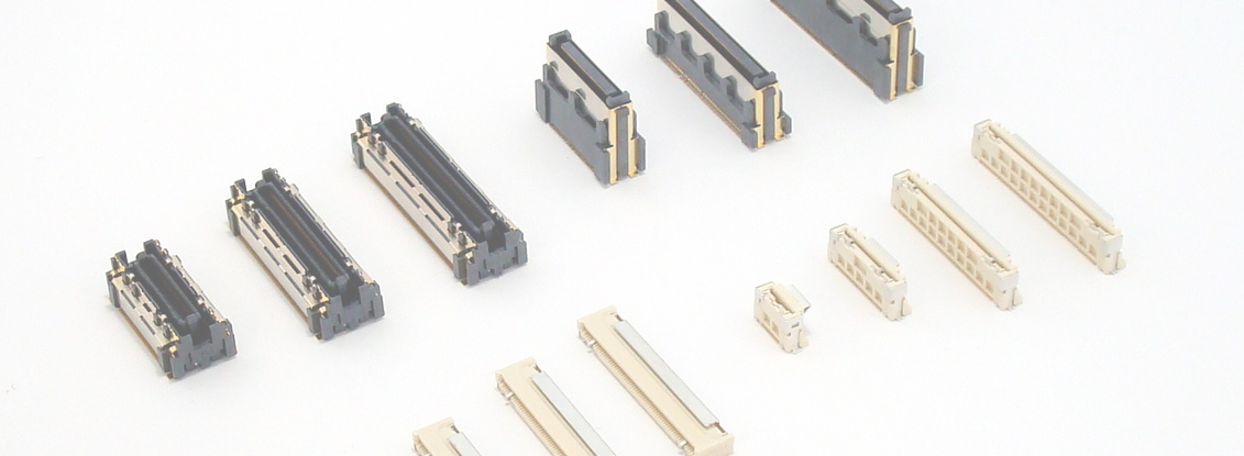
The enemies of the connector, the opponents you must fight in order to complete its function, are truly diverse. Since it is difficult just to follow the main ones in it, I will first classify them roughly and summarize them.
The role of a connector can be described as "connecting where electricity should be connected, and isolating where it should not be connected". Therefore, connection failures in connectors can be roughly divided into the following two phenomena.
・ Non-conducting (open/open) = not connecting where it should be
・Short circuit, short circuit, and incorrect connection = Connecting something that should not be connected
Looking more closely at the performance aspect, there are other factors such as degradation of high-speed signals, but let's simply focus on these two here.
All functional products have poor connections that do not function from the beginning, and poor connections that break down due to deterioration. Therefore, the timing of occurrence of connection failure in connectors can be divided into the following two types.
・ Immediately after Mating (does not function from the beginning / does not start up)
・ In continuous use (connection failure occurs during use)
Next, there are two factors that cause poor connection: human error and environmental dependence. Furthermore, the second type of environment dependency can be divided into the following three categories.
1. Poor connection due to human error
(1) Incomplete Mating
(2) Mating
2. Poor connection due to environment
(1) Poor connection due to mechanical influence
(2) Poor connection due to chemical change
(3) Poor connection due to foreign matter
The following table summarizes connector connection failures, their occurrence timing, and their causes.
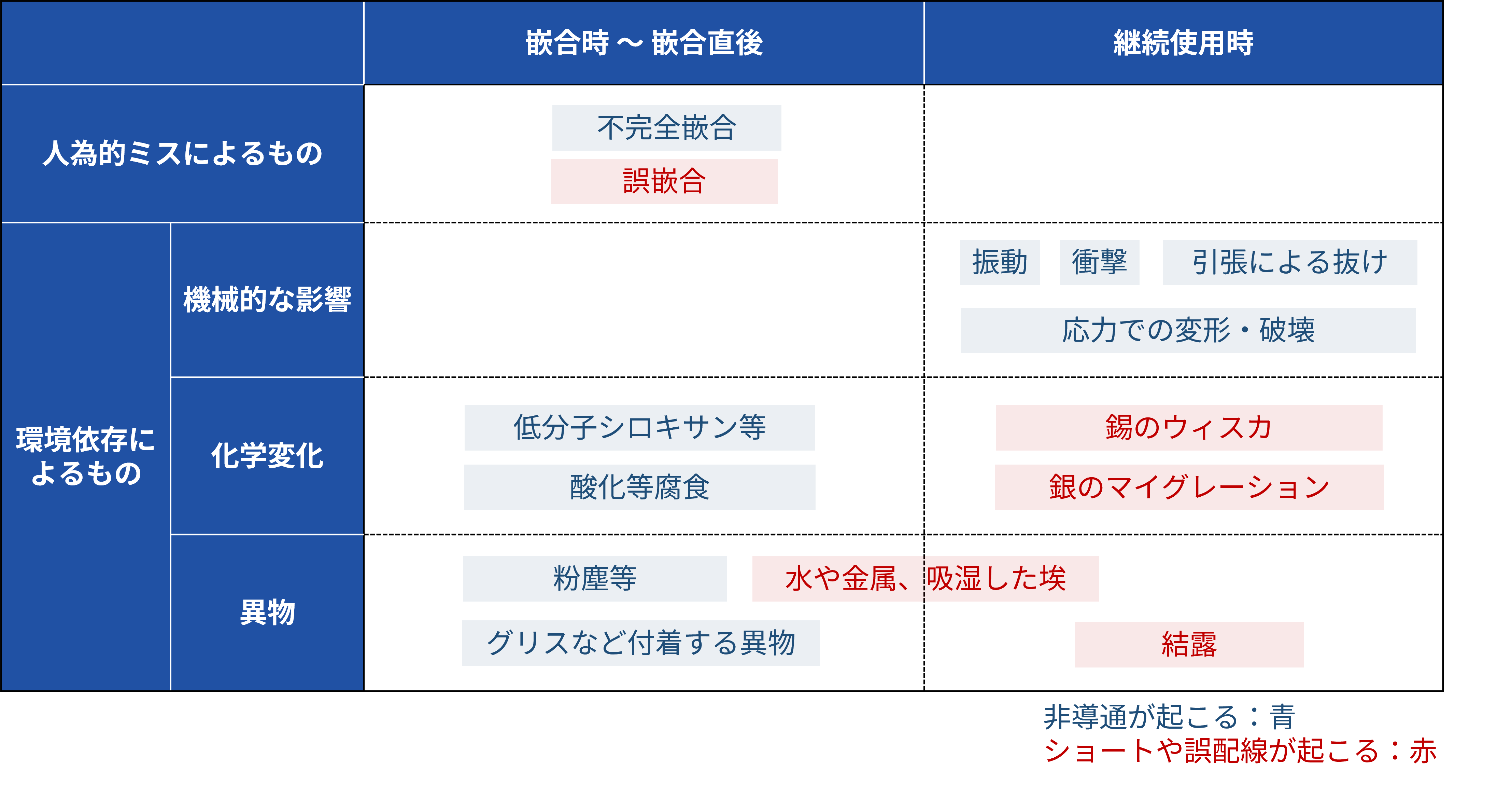
If you look closely, there are others, and I think that the classification may change depending on how you look at it, but in general, you can classify it like this. Now let's see what kind of measures are taken for each category.
People make many mistakes, including mistakes. Anyone can commit that. Of course, there are serious people who don't break even the smallest rules and careful people who make few mistakes, but there are also people who break the rules just for the sake of efficiency, and people who are lazy and repeat the same mistakes. In order to proceed well with the premise that there are various people, it is necessary to take some countermeasures.
For example, when a rule is not followed or an accidental mistake occurs, it is not only the person who violates the rule or makes the mistake that is to blame. In such a case, one of the following methods is often used to improve the system and rules.
① Disable work other than rules and procedures
② Arouse and perceive on the spot that it is in the correct state or that a mistake has occurred
③ Make the mistake itself impossible (make it okay to make a mistake)
At manufacturing sites, various measures are taken to ensure worker safety and product quality. For example, in order to prevent the operator from putting their hands into the Floating parts of the equipment, there is a mechanism to operate the machine only by pressing two buttons in separate locations with both hands. Connectors are treated in the same way.
Earlier, I mentioned imperfect Mating and incorrect Mating as connection failures caused by human error. I will explain each one.
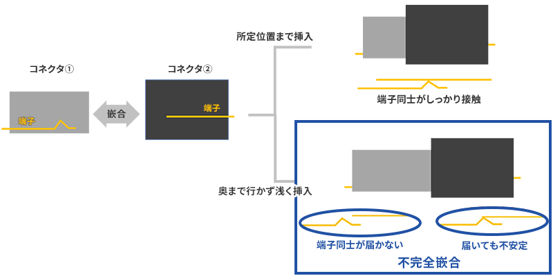
Incomplete Mating refers to the state in which the terminals in the connector do not contact each other or are in contact only unstablely because the connector is not inserted to the specified position and ends at a shallow position.
There are two countermeasures:
A common method to prevent this is to have a full Mating and a tactile click. The structure is such that the resins snap together when they are completely Mating, giving a click feeling. In addition, the sound generated at this time also makes the operator aware that Mating is complete.

This corresponds to Method 2, which is taken as an improvement of systems and rules, to evoke and perceive on the spot that the situation is correct or that a mistake has occurred. Among our products, Auto I-Lock structure series, which is also Automation Connector for automatic assembly as FPC / FFC Connectors, generates a click feeling at the moment of automatic locking. Although this product is designed for Assembly automation assembly, we have received positive feedback from several customers who assemble by hand, saying, "We have solved the problem of incomplete Mating poor connection due to work mistakes!"
In some cases, not only the tactile perception of the operator, but also the snap or click sound at the time of clicking is considered important, and is defined as Audible Click. In particular, the difference in sound pressure caused by a click to the noise environment around the work, such as wiring harnesses for automobiles, is defined in terms of dB (decibel) values. For such harness connectors, there is a test called the Audible Click test, which regulates and verifies the strength of the sound generated during Mating.
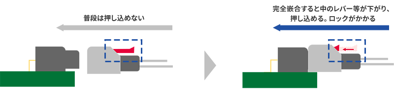
Another technique is a mechanism called CPA (Connector Position Assurance). As the name suggests, it is a mechanism to "guarantee the position of the connector", that is, a mechanism to clarify that it is "properly Mating". Recently, an electrical detection method has also been put into practical use, and a typical example is a "locking mechanism that does not engage unless it is properly Mating." For example, a locking mechanism (Fig. 3) in which a stopper, etc., is lowered by Mating so that the lever can be pushed in, or a locking mechanism that can be covered from above like a lid.
This mechanism is often applied to harness connectors and WtoB connectors. We are not preparing for the current product lineup, but we are currently considering the development of products that are applied.
Mating can be roughly divided into two cases.
・ Multiple connectors are lined up in the work environment, and they are connected to the wrong ones.
・ The connector is inserted in the wrong direction.
There are three countermeasures:
The first case is particularly likely to occur when wiring a large number of wire harnesses, such as wiring for vehicles and wiring for communication devices. Since the same connector is often used multiple times, mis-Mating can easily occur. As an ingenuity on the part of the routed side, destination labels are attached and checked by reading barcodes, etc., but the most commonly used method for connectors is to add color variations to the plastic parts that can be seen from the outside.
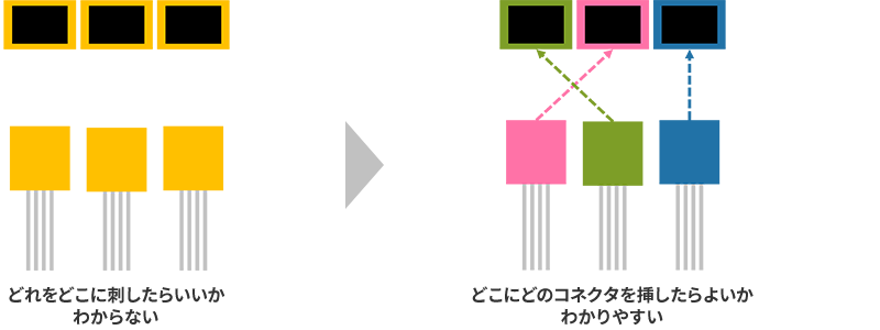
This makes it easier for workers to understand which connector to insert where, and makes it easier to find mistakes later. This is also the method used to improve the system and rules (2), "Arousing and perceiving on the spot that the situation is correct or that something is wrong."
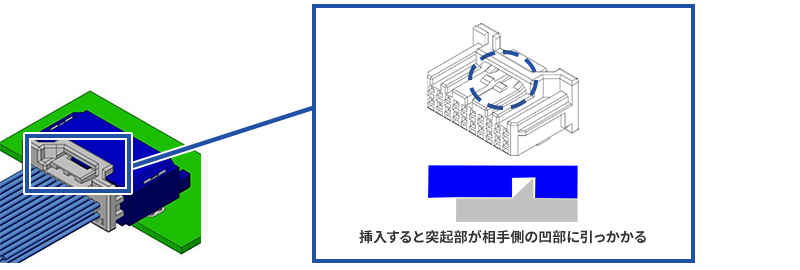
However, this still allows Mating in the wrong place just by being perceived. Therefore, in some cases, a mechanism called a key is added. A common structure is to add matching grooves and projections to the male and female connectors to be combined in addition to the basic structure of the connector, and prepare several types of them in different positions.
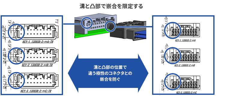
By doing this, when you try to insert it into the wrong connector, you can prevent the key from interfering and Mating.
In order to verify the effectiveness of this method, it is also used as a test to confirm that even if a certain amount of force is applied to Mating, it will not mate with other polarities and will not break. This is an approach that corresponds to Method 1, "Disable work other than rules and procedures", which is taken as an improvement of systems and rules. Our WtoB products 13065S + 13065B have 3 types of key codes, and 13103S + 13103B have 2 types of key codes.
Another mis-Mating is the mistake of inserting the connector in the wrong orientation. In most cases, this mistake is due to ignoring the resistance when inserting, or not noticing it, and destroying the connector and inserting it backwards. In order to deal with this, we have made it as easy as possible to identify the top, bottom, left, and right, and adopted a structure that prevents reverse insertion.
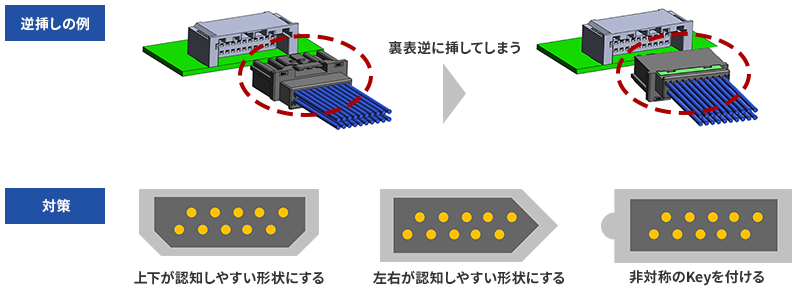
Even so, the smaller the connector, the more problems caused by reverse insertion. Under such circumstances, Apple's Lightning and USB-C appeared. This is a connector that was born from the idea of method 3, "Make mistakes impossible (make mistakes okay)", which is taken as an improvement to systems and rules. It works exactly the same even if you put it upside down. From a usability point of view, it's a great way to go. However, it requires a gimmick and a corresponding cost, so it is a method of applying the right person in the right place.
In addition, our Board to Board Connectors do not have polarity and can be Mating even if they are rotated 180° unless there is a special request for a custom product. In the case of Board to Board Connectors, the position and direction are basically determined between boards, and it is based on the idea that there will be less problems such as mounting errors if the connector does not have polarity. In this way, the method of handling changes depending on the type of connector and how it is used. Now let's move on to poor connection due to environment dependence.
Connectors are really versatile. Therefore, mechanical movement may be caused by the environment in which the product that uses the connector is placed, or by its function/mechanism. Or they may be unintentionally or intentionally hit or thrown... or treated roughly. At such times, the connector is also mechanically affected.
If this mechanical effect is too strong, it is easy to see and the entire product may be destroyed. Each product has countermeasures against it, but before that happens, there is a phenomenon called momentary disconnection as an opponent that the connector is fighting against. The term "instantaneous interruption" is used in a variety of situations. However, the momentary interruption that the connector that I will explain this time deals with is much shorter, and it is an electrical interruption at a level that humans cannot perceive, such as μsec = 1/1,000,000 second. When the impact of vibration or shock is transmitted to the connector, it will occur if the terminals are separated from each other even for a moment.
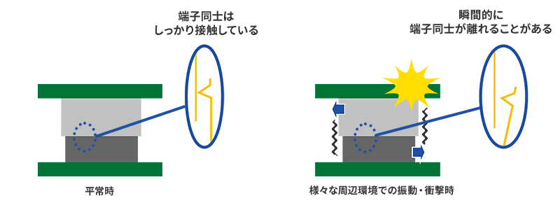
As a countermeasure, it will be a "spring that makes solid contact even if there is some trouble" design. In addition, as mentioned in "What is a connector?" and the column article "What is High heat-resistant Connector?"
We also conduct tests to confirm whether the developed connector has appropriate earthquake resistance and shock resistance performance. It is a test to actually apply vibration and shock under predetermined conditions and use an oscilloscope, data logger (used to be a pen recorder in the past), etc., to check whether a sound connection can be maintained continuously. In addition, there is also a tester called the Vibro Chamber, which conducts this under high temperature and high humidity conditions, in order to add durability due to multiple factors.
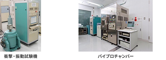
For testing equipment, please also refer to our pursuit of reliability. These test conditions correspond to various conditions, such as those specified by standards and conditions specified by customers based on their actual use. Please feel free to contact us if you have any problems with the selection or evaluation of connectors used in products used in harsh mechanical environments.
By the way, regarding vibration, there is another big opponent other than momentary interruption, and I am proud that our company was probably the first connector Board to Board Connectors board connectors. Let's talk about that next.
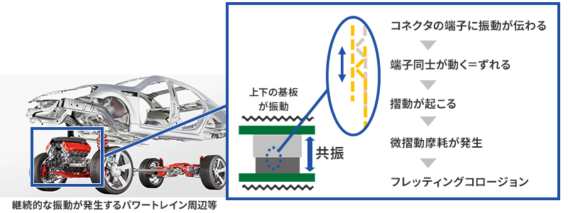
When an object is placed in a vibrating environment, the object itself vibrates. The manner of vibration is greatly influenced by the natural frequency determined according to the shape and mass of the object, causing a phenomenon called resonance.
Now let's turn our attention to the connectors used in the "placed object" and consider board-Board to Board Connectors. The upper and lower substrates connected by the connector have different resonance characteristics. Depending on the vibrations given from the surroundings, each part reacts to different frequencies or causes different resonances such as different phases. This vertical movement = deviation itself is extremely small, but if this continues, a phenomenon called fretting corrosion will occur, which will interfere with electrical connections.
As a countermeasure, it would be good if we could design the product so that it does not resonate against the expected vibration, but it seems that it is quite difficult to design parts that are exposed to continuous vibration, such as parts around the power train of an automobile. Under such circumstances, we are developing products with a Z-Move structure structure in which the contact follows the movement caused by vibration.
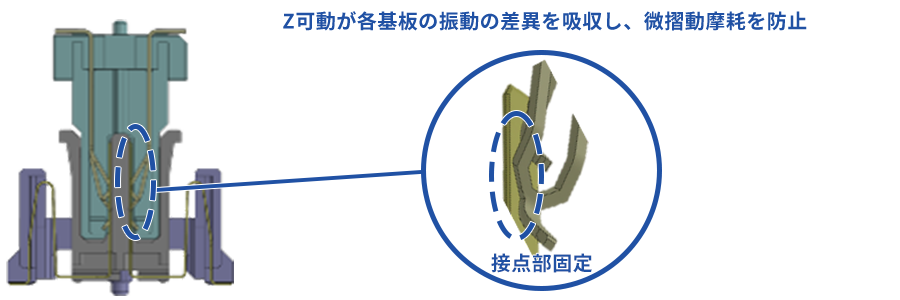
With Z-Move structure, the contacts follow up and down movement, so fretting corrosion can be suppressed. As for the resonance of the board, there is a concern that Floating Connector will break due to metal fatigue of the spring of Floating piece due to continuous movement due to vibration, but our products that use Z-Move structure are designed to withstand 100 million times of vibration.
However, even with Z-Move structure, it cannot withstand vibrations of any amplitude. Therefore, we have also implemented our own vibration analysis support that specializes in electrical connections, and along with appropriate product selection, we also offer suggestions for customer board layouts, so please make use of them.
Now let's look at connection failure due to Other mechanical influences.
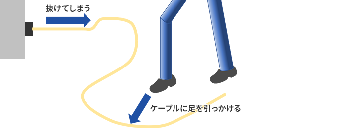
Even if it is extreme to hook it with your foot (whether it is better to withstand it or not will be discussed later), there are cases where a little stress is applied during wiring work or when something is moved, and it comes off. In order to connect electricity even under such an accident, the connector must have a certain degree of Mating retention force. It would be possible to increase the strength of the terminal connection itself, but that would make insertion difficult, so connectors with a locking mechanism have been developed.
Have you ever seen a lock with a latch mechanism like the one shown in the figure, a screw type, or a type where the main body screws in? And there are many standards that stipulate that "holding a tensile strength of XXN or more" for each application and assumed accidents. There are many examples where the minimum values for both the holding force with a lock and the holding force without a lock are stipulated in consideration of intermediate work.
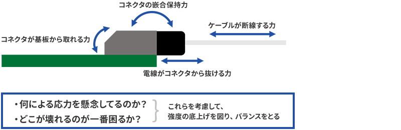
Here, depending on the standard, not only the minimum holding force but also the maximum holding force may be stipulated as "to pull out at XX N or more tension". In other words, the connector holding strength is Min. XX N & Max. YY N. Some people may think, "Isn't it better if it's strong enough?", but since connectors are mechanical parts that function as part of the final product, we shouldn't be complacent and say, "I'm fine with it!"
In other words, I'm assuming the following situation.
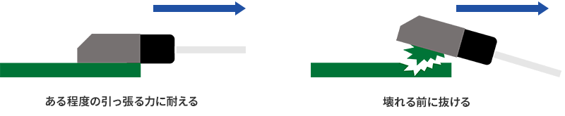
Keeping the mating Mating is important, but there is something even more important. In addition to the one shown in the figure, for example, when considering the person who caught the leg in Figure 11, it is also possible to think that it is better to pull out with a certain amount of force in order to avoid that person falling and being injured. Safety takes precedence over everything else. It may be a personal feeling, but it feels a little like the design concept of a car body, which was once made to be strong enough not to break, to a certain extent to absorb the impact of a collision, so that it collapses.
Let's consider the example above again. When the cable is pulled, it can't withstand the force and eventually pulls out.
As for the force that should be endured, the weakest part must withstand it, so each design is made to maintain strength. However, there is still a limit somewhere. Then, if it falls out next time or breaks down, I think where the risk of that happening is the lowest. If a wire is pulled out or torn off, it may lead to problems such as electric shock or short circuit of equipment. Repair seems to be difficult as the connector comes off from the board or the board itself is destroyed. Therefore, in most cases, the risk of the Mating becoming unmated is probably the lowest. Therefore, it seems to be the best for the connector to come off just before the weakest strength as a result of each effort. For this reason, there are cases where there is a provision that "it should come off when the tension is XX N or more". Even with the example given at the beginning of the mechanical accident, "the connector is pulled out by hooking the cable with your foot", it would be a problem if it came loose too much, but it would be more serious if you fell and got hurt (however, it is more important not to let the cable run where people step on it in the first place).
So far, we have focused on WtoB connectors, but the basic idea is the same for other connectors (of course, there are differences in the stress they receive). In addition to being pulled, there are various possible mechanical accidents such as rough handling and bumping into something. In such a case, we estimate the risk from the application and parts used and take measures to design it to the extent that it is robust. If you make it too sturdy, it will be big and expensive, so that is also a balance. Also, prying and twisting... We conduct and verify various nasty tests, and many of them are standardized. In addition, various customer feedbacks are also valuable information.
また頑丈にという以外でも、たとえば誘い込み構造等も、アクシデントと戦う1つの対策ですね。先の「コネクタでの人為的ミスによる接続不良と対策」の内容とも類似するものですが、無理挿しをいなして正しい位置へ誘導するこの構造も機械的なアクシデントと戦う1つの機構になります。
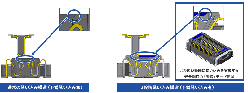
To put it plainly, luring is a structure that guides a misaligned connector to the correct position by means of a taper on the housing. Even with this small structure, various ingenuity is applied. For example, the 0.4mm pitch 10126S, etc. may have a small connector, so by providing a preliminary taper, the guiding effect is enhanced (the mating side is 10126B).
This includes whisker-like things generated from tin plating and ion migration generated from silver plating. Tin whiskers are generated by stress and their growth is accelerated by high temperature and high humidity. Ion migration of silver is a phenomenon in which a hand reaches out to pick up electrons from the positive electrode to the negative electrode. Those in their 40s and above may remember that there was a large-scale recall of HDDs due to poor connection caused by silver migration due to the red phosphorus contained in the semiconductor encapsulant (not the connector). This topic is explained in more detail in another article in the column, "Why are connector terminals plated?", so please refer to that.
It is the current situation that a perfect countermeasure is quite difficult. For example, tin whiskers can be suppressed to some extent by selecting processes and materials. It can also be blocked by the structure of the housing. Even so, it will not be zero, so the best solution is to use the right material in the right place, taking into account the usage environment and connector terminal spacing (pitch). In other words, you can specialize in the battlefields you are good at, leave the difficult parts to the gold plating, and avoid battles where you are sure to lose.
There is also what is called dissimilar metal contact corrosion (galvanic corrosion) that occurs when dissimilar metals come into contact with each other. This is mainly a problem when there is a gold-plated pinhole, etc., and it is tested with a salt spray test.
As a countermeasure, methods such as sealing are taken. Also, even in cases where corrosion due to surrounding gases is a concern, the metal, especially the material and thickness, etc., are important, and the resistance to several types of gases (SO2, H2S, NO2, Cl, etc. are popular) and their mixtures are verified by prescribed tests. We also have this testing machine, which is listed in the "Pursuing Reliability" section of our website. These are also explained in a little more detail in "Why plate the terminals of connectors?"
In addition, there is also the problem of poor contact connection due to low-molecular-weight siloxane. I've never heard of this being a problem with connectors (maybe thanks to the wiping mechanism, which I'll talk about later), but it's an occasional problem with switches, which are a relative of connectors. The problem of low-molecular-weight siloxane is an outgassing problem, and various verifications are required for severe applications. Fortunately, the LCP, PBT, etc. that we often use are engineering plastics that have almost no problem of outgassing. Even so, depending on the application, there are cases where it is necessary to verify the occurrence of outgassing and foreign substances (functional obstacles) at a very strict level, so various measures are required each time. With that in mind, let's move on to how the connector receives such foreign objects.
Connectors also fight against various foreign substances that come in contact with the connection environment and connection. Basically one of the following countermeasures will be used.
・Do not intrude
・ It will not be disturbed even if it is invaded
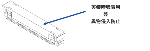
I will touch on intrusion prevention later, but an easy-to-understand example is the cap attached to the connector.
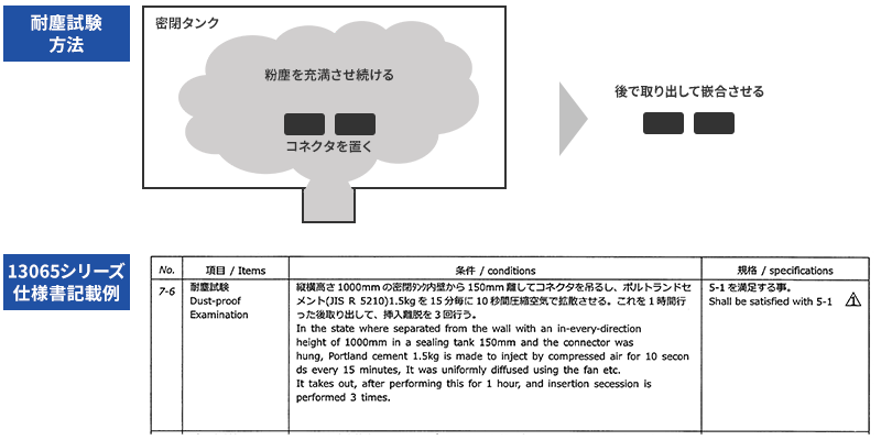
Now, let's talk about what happens if you get hacked. There are various types of foreign objects. Dust, dirt, metal, water... First, let's talk about insulators that block contact. There is a test called a dust resistance test, especially for dust, as a test when it is (or is allowed to be) intruded. In this test, the connector is exposed for a certain period of time in a dust-filled environment, and then taken out to check whether the specified performance is satisfied. There are several types of dust and they are specified.
There are foreign substances other than dust that interfere with the insulation system and connection, but wiping is the mechanism that the connector fights against them. The terminals of the connector are pressed against each other with a suitable contact pressure and are Mating while rubbing the distance called the effective Mating length. It depends on the product, but most of our representative connectors are about a few millimeters in size, so it may be difficult to perceive it as a sensation, but in the microscopic world, it is rubbing. At this time, wiping is performed.
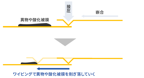
The key to fighting foreign matter by wiping is to design "contact pressure = strength" and "effective Mating = fighting time" so that it can fight foreign matter, and to design the terminal shape for efficient wiping. On the other hand, there are size restrictions, and the power required for insertion and removal cannot be increased unnecessarily, so it is difficult to achieve a winning design.
Therefore, there is a technology called 2-Point Contact structure that strengthens the weapon in a dual wielding manner. This consists of two terminals aligned in a straight line in the front and back, and the front terminal scrapes out foreign matter, and even if it gets on the foreign matter, the rear terminal will make a reliable connection.

We often receive positive feedback from customers who have had problems dealing with contaminants, and that the situation has improved significantly after adopting a connector with this structure. In subsequent inquiries, there are some customers who say that 2-Point Contact structure is a must. 2-Point Contact structure is explained in more detail in "Options for Improving Connector Reliability", so please refer to it if you are interested.
Contaminants that can cause shorts include water and other conductive liquids, metal powder, and moisture-absorbed dust. Also, if condensation occurs, there is a risk of short circuit. These issues aren't just wipes and wipes away in a humid environment. It is necessary to have a structure that makes it difficult for foreign matter to enter or that foreign matter does not straddle the electrodes.
IEC 60664-1 (Insulation Coordination of Devices in Low-Voltage Power Supply Systems) specifies Pollution Degree/Pollution Degree For environments ranked from 1 to 4 in Rated voltage is determined. The rough environment for each rank is as follows:
Pollution degree 1: in a clean environment or in closed equipment
Pollution degree 2: most common environment
Pollution degree 3: Severe environments such as factories
Pollution degree 4: outdoors where it is mainly exposed to the elements
The structure specified in IEC60664 is called surrounding material and creepage distance. The difference between clearance distance and creepage distance is imaged in the following figure.
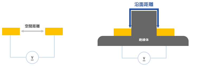
If anything, it is a set with the rated voltage because of safety standards, but the basic idea is to make it a state where "conducting objects cannot reach (difficult to reach) between electrodes". This way of thinking is common to countermeasures against various conductive foreign substances. Structural measures that are actually applied to connectors are more complicated, but I tried to illustrate the limits depending on the simple measures and the degree of the environment.
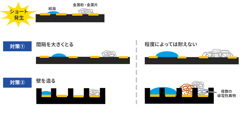
If you're concerned about short-circuit failures due to condensation or metal foreign objects, you can prevent them from reaching the exposed metal parts. By simply increasing the interval = distance or following a structure like a protective wall, it is effective against foreign matter to a certain extent. However, if a larger or larger amount of foreign matter enters than expected, trouble will occur again. If you try to create a connector that can withstand any situation, there are many cases where it becomes heavy-duty and loses its availability. Of course, there is actually a demand for heavy-duty connectors, but it is not realistic in terms of cost and size to make all of them like that.
In that sense, the assumptions raised above are very important. Each connector manufacturer is not limited to this issue, and during product development, various product specifications are carefully examined, such as "what kind of market and what kind of application will this product be used in?" I think that many of the customers who use our connectors have been asked about their applications by the sales representatives of the connector manufacturers and have seen disclaimers in the specifications. Now, for that assumption or for the countermeasures that have been adopted, we will not only verify the effects but also evaluate them. For example, condensation is verified by temperature and humidity cycle tests under various conditions. Our reliability laboratory, which appears frequently, also has such facilities and conducts evaluations of various products on a daily basis.
Finally, I would like to talk about the standards for the intrusion of foreign matter.
The IEC IP standards are well-known for stipulating the intrusion of foreign matter into products, and I think many people have heard of them. IP = International Protection, graded with IP XX and two digits. I think that the image of the waterproof standard is strong, but the first stage of XX is divided into 7 levels from 0 to 6 for protection against the human body and solid objects. Roughly speaking, the grade is determined by the size of an object that can enter (prevent entry), and the smaller the object, the higher the grade. The highest grade, 6, is completely dustproof. The second half of XX is the familiar waterproof grade. What used to be 9 levels from 0 to 8 has recently been recognized as 10 levels with the addition of 9K for jet steam cleaning in the German standard. We have listed the grades that are actually applied.
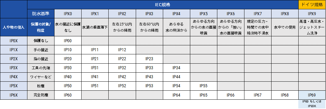
There are places in the matrix where the grade doesn't exist, but there is no IP18 because, for example, a finger can reach a dangerous place but water can't get in. It is a standard that makes it very easy to understand what kind of situation is assumed. This standard is not for parts such as Onboard Coaxial Camera Solution, but for products, and we do not refer to it directly for our products, which are mainly used in equipment.
I have explained the causes and countermeasures for poor connection. The reasons why connection is not required and countermeasures can be summarized as follows.
(1) Incomplete Mating
Countermeasures: Clicks and Audible Clicks
(2) Mating
Countermeasures: Connector color coding, Key Feature, structure that prevents reverse insertion
(1) Poor connection due to mechanical influence
Momentary interruption due to vibration or impact
Countermeasure: Spring
Microsliding wear due to vibration
Countermeasure: Z-Move structure
mechanical accident
Countermeasures: Locking mechanism, luring structure
(2) Poor connection due to chemical change
Growth from metal Whiskers, ion migration
Countermeasures: Use the right person in the right place
Galvanic corrosion (dissimilar metal contact corrosion)
Countermeasure: Sealing treatment
(3) Poor connection due to foreign matter
dust
Countermeasures: Wiping and two-point contact structure
Short circuit due to conductive liquid, metal powder, moisture-absorbed dust, etc.
Measures: IEC 60664-1
If, as a result of this column, some of you have changed your mindset from ``If metals touch each other, they conduct,'' to ``Connectors are also a problem,'' then I think that our company and those who are working hard in this industry will be rewarded a little. And not only for connectors, but also for various electronic products and electronic components, we are constantly devising and verifying even the smallest details that we are not usually aware of. I tend to forget about it, but I was reminded of the detailed technology applied to various products other than connectors and the appreciation of the people who support them.